The Real Cost of a Small Blockage
In a wet scrubber, nozzles look like small parts, but they control the liquid distribution inside the tower. When spray coverage is poor, gas contacts less liquid surface area. The result can be lower removal efficiency, higher outlet concentration, higher pressure drop, corrosion in dry zones, and unplanned shutdowns.
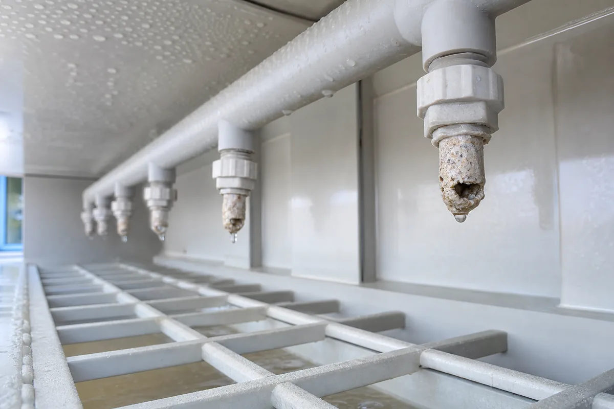
Scrubber nozzle clogging is common in acid gas scrubbers, alkali scrubbers, packed-bed scrubbers, spray towers, and exhaust systems with dust or crystallizing chemicals. The blockage usually does not happen suddenly. It often starts as partial plugging, uneven spray, or reduced flow from one branch pipe. Operators may only notice it when the stack reading changes or the fan load increases.
Typical warning signs include:
- Higher pH or lower pH consumption than normal at the same gas load
- Outlet concentration increasing while pump pressure looks normal
- Pump discharge pressure increasing, but flow decreasing
- Dry areas on packing, demister, or tower wall
- Uneven mist pattern during inspection
- More scale found in the circulation tank
- Frequent blockage at the same nozzle position
A useful rule of thumb: if 10–20% of nozzles are partially blocked, the scrubber may still “look” operational, but gas-liquid contact can already be seriously uneven. For packed towers, poor liquid distribution can also create channeling through the packing bed.
Main Causes of Scrubber Nozzle Clogging
Most nozzle clogging comes from one or more of four sources: suspended solids, chemical precipitation, biological growth, or mechanical design problems.
1. Suspended solids in the scrubbing liquid
Dust from the exhaust stream, corrosion particles, welding slag, plastic chips, and packing fragments can collect in the circulation tank. If these solids are larger than the nozzle free passage, clogging is predictable.
For many PP scrubbers, common nozzle orifice sizes are in the range of 3–10 mm, depending on flow rate and spray pattern. A safe design rule is:
`text Maximum particle size should be less than 1/3 of the nozzle minimum free passage. `
For example, if the smallest nozzle opening is 6 mm, particles larger than about 2 mm should be removed before the pump discharge reaches the spray header.
2. Chemical precipitation and scaling
Scaling is very common in scrubbers handling acid gases, alkaline fumes, ammonia, fluoride, sulfur compounds, or process exhaust containing salts. When pH, temperature, and concentration change, dissolved solids can precipitate.
Examples include:
- Calcium carbonate scale from hard make-up water
- Calcium sulfate scale in sulfate-rich systems
- Sodium chloride or other salt crystallization at high TDS
- Silica scaling in some wastewater or process vapor applications
- Reaction solids from neutralization, such as fine gypsum-like particles
High evaporation increases salt concentration. If blowdown is too low, total dissolved solids rise until crystals form. These crystals often first appear at the nozzle tip because pressure drops and liquid films become thin there.
A practical control point is electrical conductivity. The exact limit depends on the chemistry, but many scrubber systems operate better when conductivity is controlled by blowdown instead of allowed to rise continuously. Operators should record normal conductivity during stable operation and set an alarm above that baseline.
3. Biological growth
In warm scrubbers with organic vapors, low oxidant levels, or stagnant sections, biological slime can grow in the tank, pipe branches, and nozzle body. This is common when the scrubber handles low-concentration odor, food process exhaust, or wastewater-related gas.
Biofilm does not always block the nozzle alone. It catches dust and small crystals, forming a soft plug. If the nozzle is cleaned and then clogs again within days, biological fouling should be considered.
4. Poor hydraulic or mechanical design
Sometimes the liquid is clean enough, but the piping layout creates clogging risk.
Common design problems include:
- Dead legs in spray header piping
- No drain point at the end of horizontal headers
- Low flow velocity in large branch pipes
- Pump suction too close to tank bottom sludge
- No strainer before the pump or nozzle header
- No access ports for inspection and cleaning
- Nozzle type selected with too small a free passage
For recirculation piping, a common target velocity is 1.5–2.5 m/s. Below about 1 m/s, solids can settle in horizontal pipework. Above about 3 m/s, friction loss, pump energy, and erosion risk increase. These numbers depend on liquid density, solids loading, and pipe material, but they are good starting points.
Nozzle Type, Strainer, and Liquid Quality: What to Match
There is no universal “anti-clog” nozzle. The correct choice depends on gas flow, tower diameter, packing type, liquid flow, solids content, and required droplet size. However, the relationship between nozzle type and clogging risk is clear.
| Item | Lower clogging risk | Higher clogging risk | Engineering note |
|---|---|---|---|
| Nozzle passage | Large free passage, simple internal path | Small orifice, narrow swirl slots | Choose the largest passage that still gives required spray coverage |
| Spray type | Full cone or spiral nozzles with open structure | Fine mist nozzles with small holes | Fine droplets improve contact but clog more easily |
| Liquid solids | Filtered, low suspended solids | Dusty, scaling, sludge carryover | Measure suspended solids, not only pH |
| Header layout | Sloped or drainable, with flushing points | Dead-end horizontal branches | Add drain/flush valves at low points |
| Tank design | Sloped bottom or easy sludge removal | Flat tank with pump suction near sludge | Keep suction above settled solids |
| Maintenance | Routine inspection and flushing | Clean only after failure | Preventive cleaning is usually faster than shutdown cleaning |
For many wet scrubbers, a basket strainer or Y-strainer is installed before the pump or after the pump discharge. Mesh size must be selected carefully. If the mesh is too fine, it blocks often and starves the pump. If too coarse, nozzle clogging continues.
A practical starting point:
`text Strainer opening ≤ 1/3 to 1/2 of nozzle minimum free passage `
Example: for a 6 mm nozzle passage, a strainer opening of 2–3 mm is often reasonable. If the liquid has fibrous material or sticky solids, a larger strainer with more open area may be needed to reduce cleaning frequency.
Also check strainer open area. The total open area should normally be several times larger than the pipe cross-section. If not, pressure drop rises quickly as debris accumulates.
Operating Controls That Reduce Clogging
Good operation is usually more effective than frequent emergency cleaning. The following controls help stop scrubber nozzle clogging before it becomes a shutdown problem.
Control pH within a stable band
For acid gas scrubbing with caustic solution, many systems operate around pH 8–10, but the correct value depends on target gas, outlet limit, and chemical reaction. Running pH too high can increase scaling risk in some water chemistries. Running too low can reduce removal efficiency and cause corrosion in downstream equipment.
Avoid large pH swings. A pH probe with poor calibration may overdose chemicals and create precipitation. Calibrate pH instruments regularly, especially in high-salt liquid.
Maintain blowdown and make-up water
Blowdown removes dissolved salts and fine suspended solids. If no blowdown is used, concentration will rise until scaling or crystallization occurs.
A simple concentration estimate is:
`text Cycles of concentration = Conductivity of circulating liquid / Conductivity of make-up water `
If make-up water is 500 µS/cm and circulation water is 5,000 µS/cm, the system is at about 10 cycles. Whether that is acceptable depends on the salt chemistry. Hard water and high sulfate or silica may require lower cycles.
Remove sludge from the tank
Do not rely on the pump to “keep solids moving.” In many scrubbers, solids settle in corners, then enter the pump during flow disturbance or tank cleaning. Provide and use a sludge drain.
A practical maintenance rule:
- Inspect tank bottom at least monthly during early operation.
- If sludge depth exceeds 50–100 mm, remove it before it reaches the pump suction zone.
- After stable history is known, adjust the interval based on actual solids accumulation.
Keep enough liquid flow
Nozzle spray pattern depends on pressure and flow. If pump flow is too low, droplets become larger and distribution becomes uneven. If pressure is too high, fine droplets may increase mist carryover and demister load.
Many plastic scrubber spray systems operate with nozzle pressures around 0.1–0.3 MPa. Some nozzle types need lower or higher pressure. Always check the nozzle curve, because flow follows approximately:
`text Q2 = Q1 × √(P2 / P1) `
If a nozzle delivers 10 L/min at 0.2 MPa, then at 0.1 MPa it delivers:
`text 10 × √(0.1 / 0.2) = 7.1 L/min `
That is a 29% flow reduction, not a small change.
Maintenance Method: Clean the System, Not Only the Nozzle
If clogged nozzles are removed, washed, and reinstalled without solving the root cause, the problem returns. A complete cleaning procedure should include the tank, pump suction, strainer, spray header, and nozzles.
A practical shutdown cleaning sequence:
- Stop chemical dosing and isolate the scrubber safely.
- Drain circulation liquid according to site waste handling rules.
- Open tank inspection cover and remove settled sludge.
- Clean pump suction screen or foot valve if installed.
- Remove and clean the strainer basket or mesh.
- Flush spray headers from the end drain valves, not only from the pump side.
- Remove nozzles and check each free passage under light.
- Reinstall nozzles in the correct orientation.
- Refill with clean water and test spray pattern before restarting chemical operation.
- Record pressure, flow, pH, conductivity, and visual spray condition as the new baseline.
For mineral scale, mechanical cleaning may not be enough. Acid cleaning can dissolve carbonate scale, but chemical cleaning must be selected based on materials and deposits. PP equipment has good resistance to many acids and alkalis, but pumps, seals, gaskets, instruments, and metal fasteners may not. Always check compatibility before chemical circulation cleaning.
If nozzles clog repeatedly in the same branch, inspect header slope and internal deposits. If nozzles clog randomly, look at tank solids, strainer bypass, or precipitation.
Practical Next Step
To solve scrubber nozzle clogging, collect four data points before changing parts: nozzle type and orifice size, pump pressure and flow, circulating liquid conductivity, and suspended solids or sludge condition. Then compare the particle size and strainer opening with the nozzle free passage.
If you are specifying a new scrubber or modifying an existing one, provide the gas composition, dust loading, liquid chemistry, water quality, and expected operating hours. With these details, the nozzle, strainer, tank drain, and spray header layout can be selected to reduce clogging from the start.