Start With the Exhaust Problem, Not the Equipment
A coating line can produce a difficult exhaust stream: high air volume, low-to-medium VOC concentration, solvent peaks during coating changeover, mist from coating droplets, and sometimes heat from drying ovens. A good coating line VOC treatment system should not be selected by equipment name first. It should be built as a treatment train based on the exhaust data.
For most coating, printing, laminating, and surface finishing lines, the main design questions are:
- What is the exhaust air volume? Typical small lines may be 5,000–20,000 m³/h. Large multi-zone coating lines can exceed 50,000–150,000 m³/h.
- What is the VOC concentration? Many coating exhausts are in the range of 100–2,000 mg/m³, but peaks may be several times higher.
- Are the solvents water-soluble, polar, chlorinated, or high-boiling?
- Is there paint mist, resin aerosol, plasticizer, dust, or oil in the exhaust?
- Is the air hot, humid, or corrosive?
- Is the process continuous, batch, or intermittent?
The wrong approach is to install only one device and expect it to solve all problems. For example, an activated carbon adsorber may work well for clean, dry solvent vapour, but it will lose capacity quickly if coating mist and sticky resin reach the carbon bed. A wet scrubber can remove some soluble vapours and particles, but it will not remove most hydrophobic VOCs effectively. A combustion system can handle many VOCs, but it may need concentration control, safety design, and heat recovery to reduce operating cost.
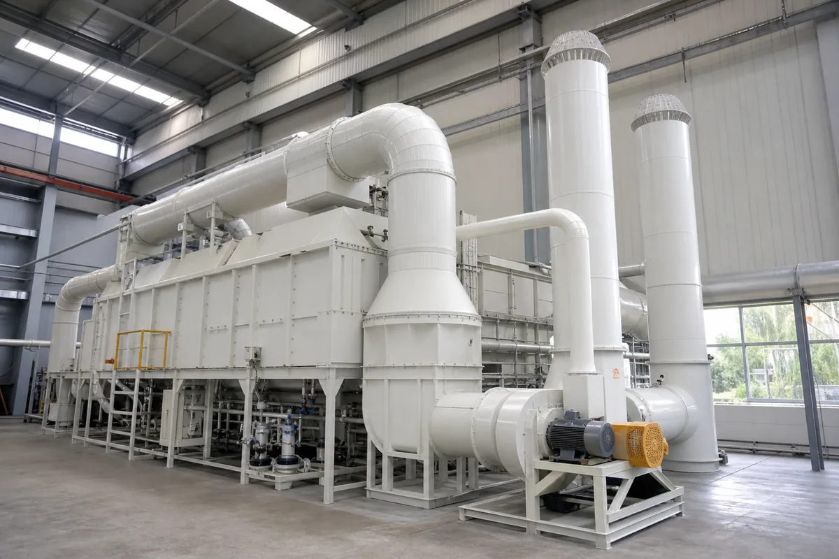
The most reliable solution is usually a train: capture hood or oven exhaust → duct balancing → mist/particle removal → cooling or humidity control if needed → adsorption, concentration, oxidation, or combined treatment → fan and stack.
Measure the Load: Airflow, VOC Mass, and Peak Conditions
Before selecting equipment, calculate the VOC mass load. The basic formula is:
`text VOC mass load (kg/h) = airflow (m³/h) × VOC concentration (mg/m³) ÷ 1,000,000 `
Example:
`text 30,000 m³/h × 500 mg/m³ ÷ 1,000,000 = 15 kg/h VOC `
This number is more useful than concentration alone. A small exhaust with high concentration may be easier to treat than a very large exhaust with low concentration.
For coating lines, also check the solvent usage balance:
`text Estimated VOC emission (kg/h) = coating consumption (kg/h) × solvent fraction × evaporation ratio `
If a line uses 100 kg/h of coating with 45% solvent, and 90% of the solvent evaporates into the exhaust:
`text 100 × 0.45 × 0.90 = 40.5 kg/h VOC `
If the measured exhaust only shows 15 kg/h, the missing solvent may be escaping from open tanks, coating heads, room ventilation, or temporary peaks not captured during testing.
Important design values include:
- Normal airflow and maximum airflow
- Average VOC concentration
- Peak VOC concentration, especially during start-up, cleaning, coating change, and oven temperature rise
- Solvent list, including boiling point and lower explosive limit
- Temperature, usually ambient to 80°C for room/hood exhaust, and sometimes 100–200°C for oven exhaust
- Relative humidity
- Particulate or mist content
- Operating hours, for example 8 h/day, 16 h/day, or 24 h/day
As a rule of thumb, for safety, keep VOC concentration in ducts and treatment equipment well below the lower explosive limit. Many designs use a control target below 25% LEL, but the exact requirement depends on local rules, solvent type, instrumentation, and equipment design.
Choose the Right Treatment Route
Different VOC control technologies have different strengths. The best choice depends mainly on airflow, concentration, solvent type, and whether the exhaust is clean.
| Treatment option | Suitable condition | Main advantage | Main limitation |
|---|---|---|---|
| PP wet scrubber | Water-soluble gases, acid/alkali fumes, some mist | Corrosion resistant, good for pretreatment | Poor removal for many hydrophobic solvents |
| Demister/filter + activated carbon | Clean, dry, low-to-medium VOC concentration, intermittent lines | Simple operation, good for many solvents | Carbon replacement/regeneration needed; sensitive to mist and humidity |
| Zeolite rotor concentrator + oxidizer | Large airflow, low VOC concentration, continuous operation | Reduces oxidation air volume, saves fuel | Higher system complexity; needs clean inlet gas |
| RTO/RCO oxidation | Medium-to-high VOC load, continuous lines | High VOC destruction when properly designed | Needs temperature control, safety design, and energy balance |
| Condensation | High concentration, recoverable solvent, low airflow | Solvent recovery possible | Often not enough alone for low-concentration exhaust |
| Wet scrubber + carbon | Mixed mist/odor/VOC with corrosion risk | Protects carbon and ductwork | Wastewater handling required |
For many coating lines, these are common treatment trains:
- Low concentration, clean exhaust
- Pre-filter or demister
- Activated carbon adsorber
- Corrosion-resistant fan
- Stack
- Large airflow, low VOC, continuous production
- Mist filter or dry filtration
- Zeolite rotor concentrator
- Small RTO/RCO for concentrated stream
- Main fan and stack
- Sticky coating mist plus VOC
- Washable pre-filter or wet scrubber
- Demister
- Carbon adsorber or oxidation system
- Fan and stack
- Oven exhaust with higher VOC concentration
- Heat-resistant duct
- LEL monitoring and dilution/control if needed
- RTO/RCO or direct oxidation
- Heat recovery if suitable
Activated carbon is often selected because it is easy to understand and install. However, the carbon bed must be sized correctly. Typical superficial gas velocity through a carbon bed is often 0.2–0.6 m/s, depending on carbon type, bed depth, pressure drop, and contact time. Common empty bed contact time is around 0.5–2.0 seconds. For difficult VOCs or strict outlet requirements, longer contact time may be needed.
For zeolite rotor systems, concentration ratio is commonly in the range of 5:1 to 20:1, depending on solvent type, inlet concentration, desorption temperature, and safety limits. A high concentration ratio is not always better, because it may create an unsafe or unstable concentrated stream.
Do Not Ignore Pretreatment and Duct Design
Many coating line VOC treatment failures start before the main equipment. Coating overspray, resin dust, and condensed solvent can block filters, poison carbon, foul rotors, and create fire risk.
Good pretreatment usually includes:
- Capture hoods close to the emission point, without disturbing coating quality
- Balanced duct branches with dampers and measuring ports
- Drain points at low duct sections if condensation may occur
- Access doors for cleaning sticky deposits
- Mist eliminators or filters before adsorption or rotor equipment
- Temperature control to prevent condensation on carbon or inside ducts
- Spark/fire protection measures where process risk requires them
Duct velocity is also important. For general VOC exhaust without heavy particles, many systems use 10–18 m/s in main ducts. If coating mist or dust is present, higher velocity may help transport contaminants, but too high velocity increases pressure drop and noise. For PP ducting, mechanical support and thermal expansion should be considered, especially on long horizontal runs.
Pressure drop affects fan power. Fan power can be estimated by:
`text Fan power (kW) = airflow (m³/s) × total pressure (Pa) ÷ fan efficiency ÷ 1000 `
Example:
`text 30,000 m³/h = 8.33 m³/s Total pressure = 2,500 Pa Fan efficiency = 0.65
Power = 8.33 × 2,500 ÷ 0.65 ÷ 1000 = 32 kW `
If poor duct design adds 1,000 Pa pressure drop, the extra power may be about:
`text 8.33 × 1,000 ÷ 0.65 ÷ 1000 = 12.8 kW `
For a line running 6,000 h/year, that is 76,800 kWh/year additional electricity. This is why correct duct sizing, filter selection, and pressure drop control directly affect payback.
Where the Payback Comes From
A treatment train “pays back” when it reduces operating cost, avoids production interruptions, and extends media or equipment life. For coating line VOC treatment, the main payback factors are usually practical, not theoretical.
Key areas to check:
- Lower fan energy
- Avoid oversized airflow.
- Separate high-concentration oven exhaust from large low-concentration room ventilation where possible.
- Use VFD control when line speed or production mode changes.
- Longer carbon or filter life
- Remove mist before carbon.
- Keep humidity and temperature within the adsorbent’s suitable range.
- Use lead-lag carbon vessels if stable outlet control is required.
- Reduced fuel for oxidation
- Concentrate large low-VOC airflow before oxidation when suitable.
- Recover heat from RTO/RCO systems.
- Keep unnecessary fresh air out of the exhaust.
- Less downtime
- Provide bypass or parallel filters for maintenance where production cannot stop.
- Install differential pressure gauges across filters, scrubbers, and carbon beds.
- Include sampling ports before and after main equipment.
- Lower waste handling
- Do not use a wet scrubber if it only transfers VOC into wastewater without real removal.
- Consider whether spent carbon, sludge, or wastewater treatment is manageable at the plant.
One useful rule: do not design only for the average day. Design for the worst normal production condition, then create operating modes for lower load. For example, a coating line may normally operate at 40% solvent load, but cleaning and colour change may create short peaks. If these peaks are ignored, outlet odor, high carbon temperature, or alarm trips may occur.
Instrumentation is part of the payback. At minimum, consider:
- Differential pressure transmitters or gauges
- Fan current or power monitoring
- Temperature sensors before and after adsorbers or oxidizers
- VOC or LEL monitoring where solvent concentration can approach unsafe levels
- Flow measurement points for commissioning and balancing
Practical Next Step
Prepare a one-page exhaust data sheet before requesting equipment selection. Include airflow for each exhaust point, solvent list, VOC concentration or solvent consumption, temperature, humidity, operating hours, and any mist or dust problem. With these values, a supplier can compare scrubber, activated carbon, rotor concentration, and oxidation options on the same basis and build a treatment train that fits the real coating line instead of only the catalogue size.