Start With the Gas Stream, Not the Equipment
Good voc abatement technology selection starts with the exhaust data. Many problems happen when a plant chooses the equipment first and checks the gas conditions later. VOC systems are sensitive to concentration, flow variation, humidity, temperature, dust, and chemical composition.
Before comparing technologies, collect these basic values:
- Airflow rate: normal and maximum, in m³/h or Nm³/h
- VOC concentration: average and peak, usually mg/m³, ppmv, or g/Nm³
- VOC composition: solvent name or CAS number if possible
- Lower explosive limit (LEL): for each major solvent
- Temperature: normal and maximum, °C
- Relative humidity or water content
- Dust, mist, oil, resin, or tar content
- Operating schedule: continuous, batch, seasonal, or intermittent
- Required outlet target: legal limit, internal target, or odor control target
- Available utilities: electricity, steam, natural gas, compressed air, cooling water
A useful first calculation is VOC mass loading:
`text VOC mass flow (kg/h) = airflow (m³/h) × VOC concentration (mg/m³) ÷ 1,000,000 `
Example: 20,000 m³/h × 300 mg/m³ ÷ 1,000,000 = 6 kg/h VOC
This number is more useful than concentration alone. A low concentration with very high airflow can still create a large solvent load. A high concentration with small airflow may be better treated by recovery or concentration before destruction.
For safety, many designs keep the inlet VOC concentration below 25% of LEL for normal operation, with alarms and interlocks at lower setpoints depending on the process risk. If the exhaust can have sudden solvent peaks, do not rely only on average concentration.
Main VOC Technologies and Where They Fit
The table below gives a practical comparison. Exact performance depends on solvent type, inlet stability, equipment design, operation, and maintenance.
| Technology | Typical best-fit range | Strengths | Limits and cautions |
|---|---|---|---|
| Activated carbon adsorption | Low to medium concentration, often below 1–2 g/Nm³; intermittent or moderate flow | Simple operation, good for many solvents, can polish low concentration gas | Not suitable for high humidity or high-boiling sticky organics; carbon fire risk for some compounds; media replacement or regeneration required |
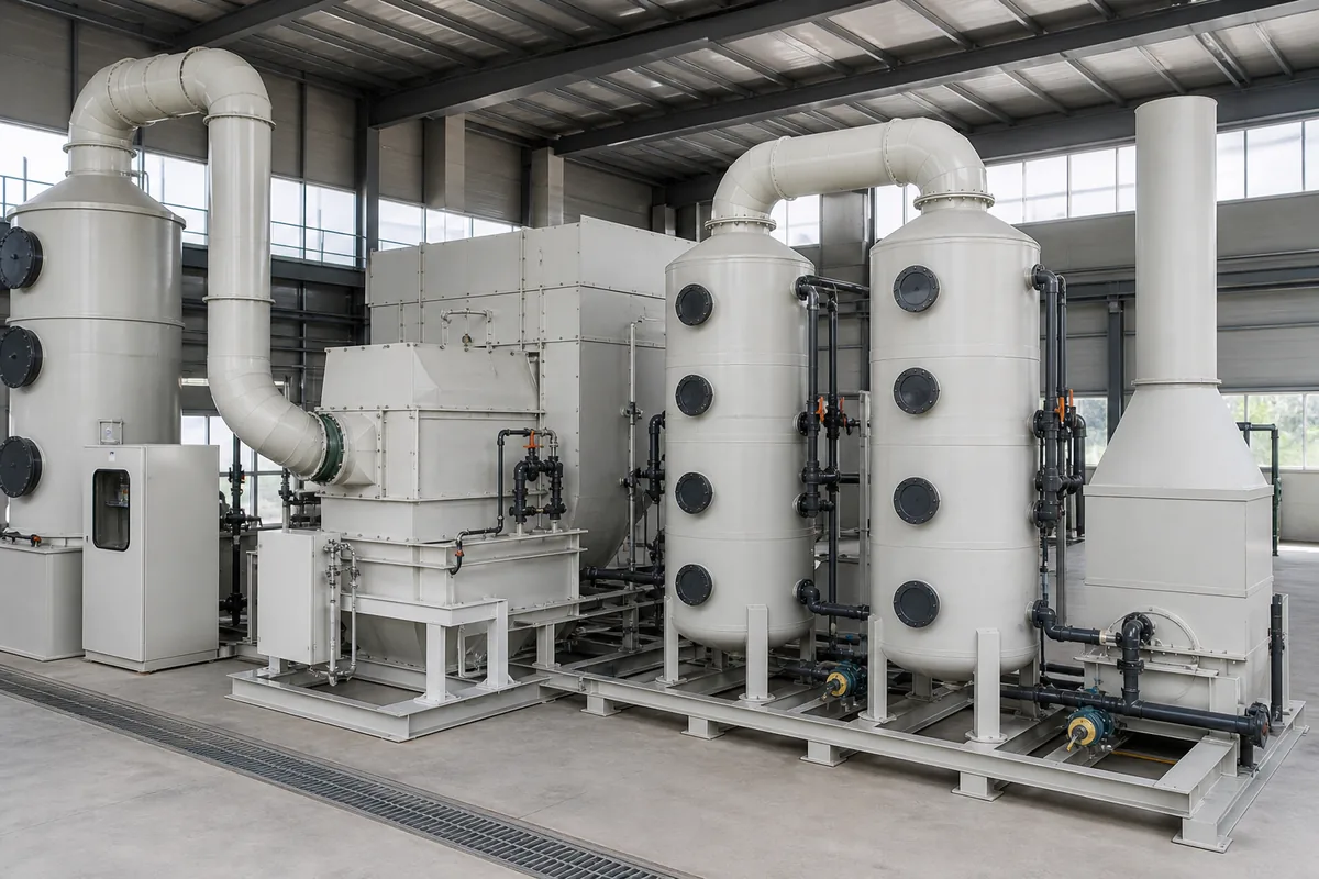
| Water or chemical scrubber | Water-soluble VOCs or reactive gases; also for acid/alkali pretreatment | Good for HCl, NH₃, alcohols, some soluble compounds; PP construction is corrosion-resistant | Poor for most hydrophobic VOCs such as toluene, xylene, hexane; creates wastewater |
| Thermal oxidizer / direct combustion | Medium to high VOC loading; stable flow | High destruction efficiency when correctly designed; handles many VOC mixtures | High fuel use at low concentration; high temperature materials required; needs safety controls |
| Regenerative thermal oxidizer (RTO) | Large airflow, low to medium concentration, continuous operation | High heat recovery, commonly 90–95%+ thermal efficiency depending on design | Sensitive to dust, silicone, phosphorus, halogens; higher complexity and footprint |
| Catalytic oxidizer | Lower temperature oxidation, clean gas streams | Lower operating temperature than thermal oxidation | Catalyst poisoning by sulfur, chlorine, silicone, heavy metals; catalyst replacement required |
| Zeolite rotor concentrator + oxidizer | Very large airflow with low VOC concentration, often below 500–1000 mg/m³ | Reduces oxidizer size and fuel consumption | Not for high-boiling, polymerizing, or sticky VOCs; needs stable humidity and filtration |
| Condensation | High concentration solvent vapor, often several g/Nm³ or above | Solvent recovery possible; useful before adsorption or oxidation | Poor for very dilute gas; cooling energy can be high; outlet usually needs polishing |
No single technology is best for every plant. The correct choice is usually based on three questions:
- Is the VOC recoverable or should it be destroyed?
- Is the exhaust dilute and large, or concentrated and small?
- Are there contaminants that will damage adsorbent, catalyst, ceramic media, or ducting?
A Practical Decision Framework
1. Check whether wet scrubbing can solve the problem
Wet scrubbers are sometimes requested for all “waste gas,” but they do not remove all VOCs well. They work when the contaminant is soluble or reacts with the scrubbing liquid.
Good candidates include:
- Methanol, ethanol, acetone: partly soluble, but removal depends on concentration, liquid rate, and packing height
- Ammonia: acid scrubbing is effective
- HCl, HF, SO₂, alkaline gases: chemical scrubbing is common
- Some amines and water-soluble odors
Poor candidates include:
- Toluene, xylene, benzene, styrene
- Hexane, heptane and many aliphatic hydrocarbons
- Many chlorinated solvents
- Oily mist without proper demister and wastewater treatment
For packed PP scrubbers, common design ranges are:
- Superficial gas velocity: 1.0–2.0 m/s through tower section
- Liquid-to-gas ratio: often 1–5 L/m³, higher for difficult absorption
- Pressure drop: typically 800–2000 Pa for packed scrubber plus demister, depending on packing depth and gas velocity
- pH control: usually required for acid or alkali gas absorption
If the VOC has low water solubility, a scrubber may still be useful as pretreatment to remove acid gas, dust, or water-soluble components before carbon adsorption, RTO, or catalytic oxidation.
2. Consider activated carbon for low concentration and clean exhaust
Activated carbon adsorption is often selected for painting, printing, coating, laboratory exhaust, electronics, and chemical storage tank venting. It is suitable when the gas is relatively cool, clean, and not saturated with moisture.
Rules of thumb:
- Gas temperature: preferably below 40°C; adsorption capacity drops as temperature rises
- Relative humidity: preferably below 70%; high humidity competes for adsorption sites
- Face velocity through carbon bed: commonly 0.2–0.6 m/s
- Empty bed contact time: often 0.5–2.0 seconds
- Typical working adsorption capacity: often 5–20% of carbon weight for many solvents, but can be much lower for weakly adsorbed compounds
Carbon systems need careful fire risk review. Ketones, aldehydes, high concentration solvents, and oxidizing compounds may create heat release in the bed. Temperature monitoring, spark prevention, grounding, and correct replacement intervals are important.
For continuous high solvent load, disposable carbon can become uneconomical and operationally difficult because replacement frequency becomes too high. In that case, consider steam regeneration, nitrogen regeneration, condensation, or oxidation.
3. Use oxidation for non-recoverable VOC mass
If the plant does not need solvent recovery, oxidation is often used to convert VOCs into CO₂ and H₂O. For chlorinated, sulfur-containing, or nitrogen-containing VOCs, the by-products may include HCl, SO₂, NOx, or other acid gases, so downstream scrubbing may be required.
Key points:
- Thermal oxidation temperature: often 750–850°C for many VOCs
- Residence time: commonly 0.5–1.0 second, depending on destruction requirement and compound type
- Catalytic oxidation temperature: often 250–450°C, depending on catalyst and VOC
- RTO ceramic bed heat recovery: often above 90% in well-designed systems, but depends on switching design and operating condition
RTOs fit large, continuous, dilute flows. However, they need good pretreatment if the gas contains dust, sticky resin, silicone oil, phosphorus, or heavy metals. These can block ceramic media or poison catalyst.
A simple heat release estimate helps judge if the VOC can support combustion:
`text Heat release (kW) ≈ VOC mass flow (kg/h) × LHV (MJ/kg) ÷ 3.6 `
For many solvents, lower heating value (LHV) is roughly 25–45 MJ/kg. If the exhaust contains 10 kg/h VOC with LHV 35 MJ/kg:
`text 10 × 35 ÷ 3.6 = 97 kW `
This heat can reduce auxiliary fuel demand. But the system still needs control for concentration peaks to avoid overheating.
Special Cases That Change the Selection
Some gas streams look simple on paper but need different treatment after checking details.
High humidity exhaust: Carbon adsorption and zeolite rotors lose performance when moisture is high. If the gas comes from washing, drying, or fermentation, consider dehumidification, heating, demisting, or wet scrubbing plus another technology.
Dust, resin, paint mist, or oil mist: Use filters, cyclones, demisters, or scrubbers before adsorption or oxidation. For paint exhaust, filter maintenance is often the main operating issue. If paint mist reaches carbon or zeolite, the media may block quickly.
Halogenated solvents: Chlorinated VOC oxidation can form HCl and sometimes chlorine-related by-products. Materials, downstream scrubber design, and wastewater treatment must be checked. PP wet scrubbers are commonly used for acid gas absorption after oxidation, but temperature must be reduced before PP equipment.
Batch processes: Batch exhaust may have short high peaks and long low periods. A buffer tank, variable-speed fan, concentration monitoring, or hybrid design may be needed. Designing only for average concentration can be unsafe.
Odor complaints at very low VOC concentration: Odor threshold may be much lower than legal VOC concentration. Activated carbon polishing or chemical scrubbing can be useful, but the media and chemical must match the odor compounds.
Hybrid Systems Are Often the Correct Answer
Many real plants need more than one technology. Common combinations include:
- PP scrubber + activated carbon: acid/alkali gas or soluble contaminants removed first, carbon polishes remaining VOC or odor
- Demister/filter + carbon adsorber: protects carbon from mist and dust
- Zeolite rotor + RTO: treats very large, dilute, continuous exhaust with lower oxidizer airflow
- Condensation + carbon: recovers bulk solvent and uses carbon for final polishing
- Oxidizer + PP scrubber: destroys VOC and removes acid gas by-products after cooling
When comparing options, do not look only at removal efficiency. Compare the full operating picture:
- Pressure drop and fan power
- Fuel or steam consumption
- Water and chemical use
- Wastewater, spent carbon, or catalyst disposal
- Maintenance access and spare parts
- Safety interlocks and online monitoring
- Plot space and duct routing
- Start-up and shutdown time
For PP ducting and fans, check gas temperature and chemical compatibility. Standard PP is usually suitable for many corrosive wet gases at moderate temperature, but it is not for high-temperature oxidizer exhaust. Hot gas should be cooled before entering PP scrubbers, PP fans, or PP ducts.
Practical Next Step
For a reliable comparison, prepare a one-page VOC data sheet with airflow, concentration, solvent list, temperature, humidity, dust/mist content, and operating schedule. Then shortlist two or three technologies using the framework above. If data is incomplete, measure the exhaust during normal and peak production before final design. This avoids undersized equipment, unnecessary energy use, and wrong media selection.