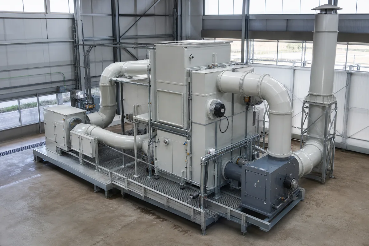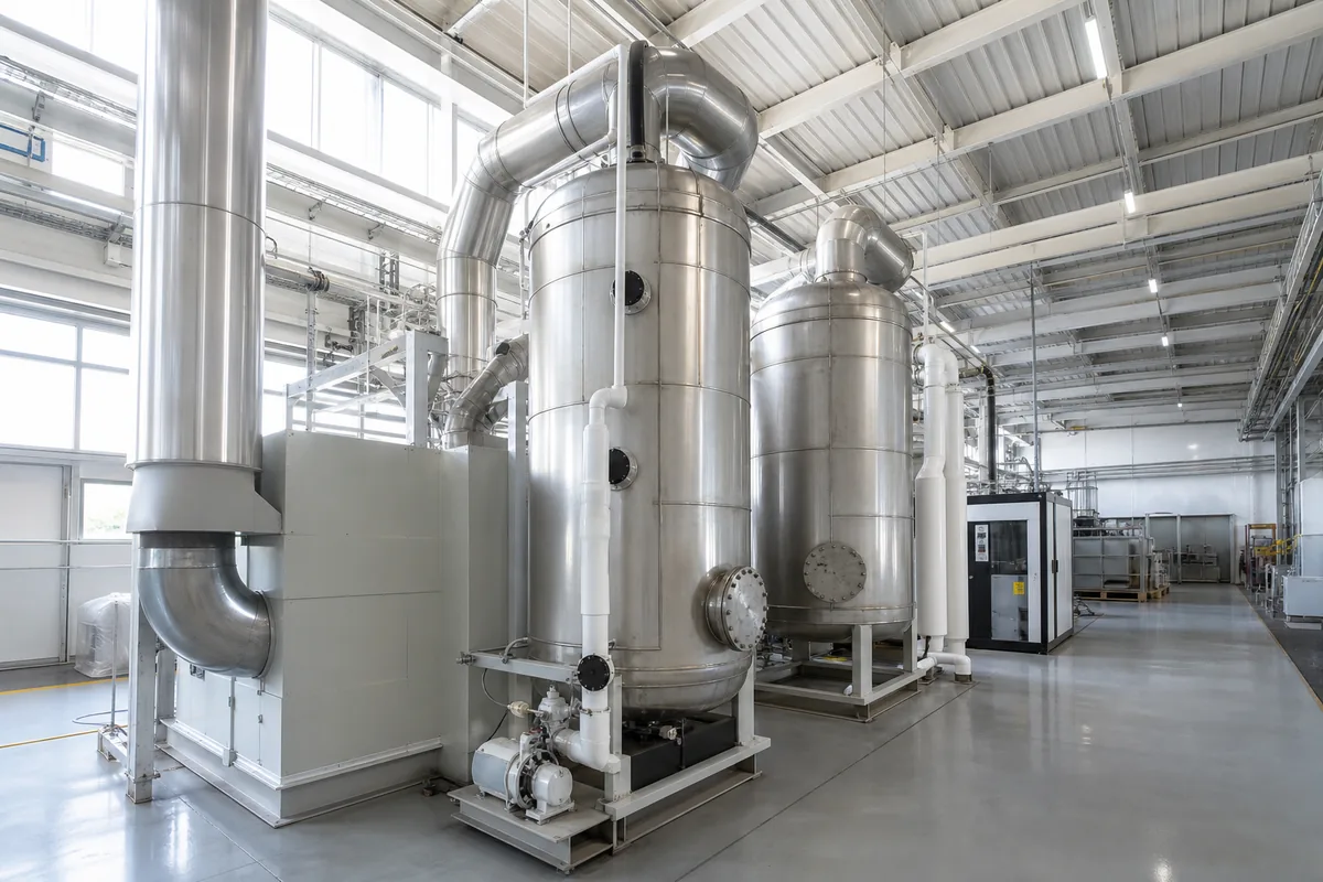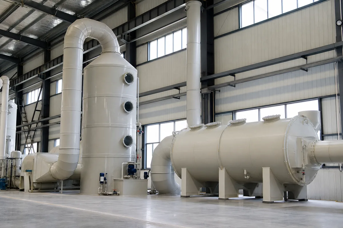
Why Orientation Matters in a Scrubber Project
When engineers compare a vertical vs horizontal scrubber, the first question is often simple: “Which one fits?” In real projects, the answer affects more than footprint. Scrubber orientation changes gas velocity, packing depth, liquid distribution, mist eliminator layout, maintenance access, fan position, duct routing, and even foundation loads.
Both vertical and horizontal wet scrubbers can remove acid gases such as HCl, HF, NH₃, SO₂, Cl₂, or alkaline mist when they are correctly designed. Both can be made from PP, FRP, stainless steel, or other corrosion-resistant materials. The difference is not that one is always more efficient. The difference is how each design uses space and how easy it is to install, operate, and maintain in a given plant layout.
For PP scrubbers used in chemical exhaust, plating lines, semiconductor support areas, laboratories, battery plants, and wastewater treatment rooms, the main selection factors are:
- Available headroom and floor area
- Exhaust air volume, usually in m³/h or CFM
- Required removal efficiency and gas-liquid contact time
- Duct inlet height and outlet direction
- Access for packing, spray nozzles, demister, pumps, and instruments
- Indoor or outdoor installation
- Structural support and wind load, if installed outdoors
A vertical scrubber is usually the default choice when there is enough height. A horizontal scrubber becomes attractive when ceiling height is limited or when the duct system already runs horizontally at low level.
Vertical Scrubbers: Compact Footprint, Higher Headroom
A vertical packed-bed scrubber normally has gas entering from the side near the bottom, moving upward through packing, spray liquid flowing downward, and cleaned gas leaving from the top through a mist eliminator. This counter-current flow is efficient because the cleanest liquid contacts the cleanest gas near the outlet, while fresh polluted gas contacts the strongest liquid near the bottom.
Typical design ranges for PP vertical packed scrubbers:
| Parameter | Common range | Notes |
|---|---|---|
| Superficial gas velocity through tower | 1.5–2.5 m/s | Lower for high mist load or strict pressure drop limits |
| Packing depth | 0.6–1.5 m per stage | Depends on pollutant solubility and required efficiency |
| Liquid-to-gas ratio | 1–3 L/m³ gas | Higher for difficult absorption or heat removal |
| Pressure drop | 800–1800 Pa | Including packing, demister, inlet/outlet losses |
| Tower diameter | Calculated from air volume and velocity | D = √(4Q / πv) using Q in m³/s |
| Total height | Often 3–8 m | Larger units may be higher |
Example: for 20,000 m³/h exhaust, convert to 5.56 m³/s. If design velocity is 2.0 m/s:
Area = 5.56 / 2.0 = 2.78 m²
Diameter = √(4 × 2.78 / 3.1416) = 1.88 m
In practice, the selected tower may be around DN1900 to DN2000 before adding wall thickness, flanges, platform requirements, and fabrication allowances.
The main advantage is footprint. A vertical scrubber with a 2 m diameter may need a base area of only about 2.5 m × 2.5 m, plus space for pump, chemical tank, access, and ducting. This is useful where floor space is expensive.
The main limitation is height. A vertical scrubber includes:
- Sump section or external circulation tank
- Gas inlet zone
- Packing support
- Packing layer
- Spray header and nozzles
- Mist eliminator
- Outlet transition
- Maintenance manholes
Even a small system can require 3 m or more total height. For indoor installation, engineers should check clear height, crane or forklift access, pipe slope, and whether the top demister can be removed. A scrubber that physically fits under the roof may still be difficult to maintain if there is no space above or beside it.
Horizontal Scrubbers: Lower Height, Larger Footprint
A horizontal scrubber usually has gas flowing horizontally through one or more spray and packing sections. The sump may be integrated at the bottom or placed separately. Mist elimination is commonly arranged near the outlet. Horizontal units are often used where the available headroom is low, such as under mezzanines, inside containerized treatment systems, or in existing workshops where ducts are already installed near ceiling level.
Typical design ranges for PP horizontal scrubbers:
| Parameter | Common range | Notes |
|---|---|---|
| Gas velocity through wet section | 1.5–3.0 m/s | Lower velocity helps reduce carryover |
| Packing depth along gas direction | 0.5–1.2 m per stage | Can use multiple stages in series |
| Liquid-to-gas ratio | 1–4 L/m³ gas | Depends on contaminant and inlet concentration |
| Pressure drop | 700–1600 Pa | Can be lower if designed with large cross-section |
| Total height | Often 1.5–3.0 m | Depends on air volume and sump arrangement |
| Length | Often 3–8 m or more | Increases with stages and access sections |
A horizontal scrubber does not escape the laws of gas velocity. If air volume is high, the cross-sectional area must still be large enough. Because height is limited, the width and length often increase. For example, if 20,000 m³/h is handled at 2.0 m/s, the required flow area is still 2.78 m². If internal height for gas flow is 1.4 m, internal width must be about:
Width = 2.78 / 1.4 = 1.99 m
After adding sump height, wall thickness, stiffeners, and service access, the installed width and length may be significant.
Horizontal scrubbers are useful when:
- Ceiling height is less than about 3.5–4.0 m
- Ducts come from process tools or hoods in a horizontal line
- The scrubber must be placed on a roof with height restrictions
- Maintenance staff prefer side access instead of top access
- Multiple treatment stages need to be arranged in series
However, liquid distribution is more sensitive in horizontal designs. Spray coverage must be checked across the full width. Drainage must avoid stagnant liquid and sludge buildup. Demister face velocity must be controlled because liquid droplets can travel directly toward the outlet if the layout is too short.
Vertical vs Horizontal Scrubber: Practical Comparison
The table below summarizes the main selection points. These are general rules; final sizing depends on gas composition, inlet concentration, temperature, target outlet concentration, and local installation limits.
| Item | Vertical scrubber | Horizontal scrubber |
|---|---|---|
| Best use case | Enough headroom, limited floor space | Low headroom, longer floor area available |
| Gas-liquid contact | Usually counter-current, efficient for absorption | Cross-flow or staged flow, can be effective with correct design |
| Footprint | Smaller | Larger |
| Height requirement | Higher, often 3–8 m | Lower, often 1.5–3 m |
| Packing maintenance | May need top or side access; lifting height important | Side access is often easier |
| Liquid distribution | Generally simpler | Requires careful spray coverage across width |
| Mist eliminator | Top outlet demister common | Outlet demister needs enough face area and drainage |
| Duct connection | May need vertical outlet duct or elbow | Convenient for straight horizontal duct runs |
| Outdoor wind load | Tall structure needs more attention | Lower profile reduces wind effect |
| Expansion for more stages | Height may increase | Length may increase |
A common mistake is selecting orientation based only on the scrubber shell dimensions. The complete system includes fan, circulation pump, chemical dosing tank, pH/ORP instruments, drain, overflow, inspection space, and duct transitions. For PP ducting, large elbows and reducers can occupy more space than expected. A 90° elbow for a large duct may require a centerline radius of 1.0–1.5 times duct diameter, depending on pressure drop and fabrication method.
Another point is fan position. If the fan is installed after the scrubber, it handles saturated clean gas and may need corrosion-resistant construction. If the fan is before the scrubber, it handles dirty gas but keeps the scrubber under positive pressure, which may increase leakage risk at inspection doors if not sealed well. Orientation affects how easily the fan connects without sharp elbows.
Layout Checks Before Final Selection
Before choosing a vertical or horizontal scrubber, collect actual layout data. Do not rely only on a building drawing if the plant already has pipes, cable trays, platforms, and other equipment installed.
Useful checks include:
- Clear height: Measure from finished floor to the lowest obstruction, not only to the roof beam.
- Maintenance space: Allow at least 600–800 mm around pumps and instruments. For manholes, 800–1000 mm is more comfortable.
- Packing removal path: Confirm whether packing can be removed through a side manhole or from the top.
- Duct slope and condensate: Wet exhaust ducts should avoid low points where liquid collects. Provide drains where needed.
- Foundation load: Include operating liquid weight. Water weighs about 1000 kg/m³; a large sump can add several tonnes.
- Chemical storage: NaOH, acid, oxidant, or other reagents need safe access and secondary containment, depending on site rules.
- Noise and vibration: Leave space for flexible connectors and fan maintenance.
- Freeze protection: Outdoor scrubbers in cold climates may need insulation, heat tracing, or indoor pump tanks.
For height-limited rooms, a horizontal scrubber may solve the main problem but create a new problem: long maintenance access along one side. For crowded outdoor platforms, a vertical scrubber may save floor area but require structural review because of height and wind load. The better choice is the one that gives stable operation and safe access for the next 5–10 years, not only the one that fits into the first drawing.
Practical Next Step
To compare options, prepare a simple layout package with exhaust flow rate, gas composition, temperature, inlet duct size and height, available floor area, clear headroom, and required outlet direction. With these data, a supplier can make both a vertical and horizontal preliminary arrangement, estimate pressure drop, check pump and fan placement, and show which scrubber orientation is safer and easier to maintain for your site.