Why Printing Plants Need a Clear VOC Strategy
In gravure, flexographic, screen printing and coating lines, VOC emissions mainly come from inks, thinners, cleaning solvents and drying ovens. Common solvents include ethyl acetate, ethanol, isopropanol, MEK, toluene and mixed hydrocarbons. A good printing plant VOC control system must handle changing solvent load, high air volume and continuous production without creating safety or maintenance problems.
For most printing plants, the main choice is:
- Solvent recovery: capture VOCs and reuse or sell the recovered solvent.
- Solvent destruction: oxidize VOCs into CO₂ and water, usually by thermal oxidation, catalytic oxidation or regenerative thermal oxidation (RTO).
Both methods can work well. The correct choice depends on solvent type, concentration, exhaust volume, operating hours, heat balance, and whether the recovered solvent has real value in your process.
A useful first calculation is the VOC mass flow:
`text VOC mass flow (kg/h) = Air flow (m³/h) × VOC concentration (mg/m³) ÷ 1,000,000 `
Example:
`text 30,000 m³/h × 2,000 mg/m³ ÷ 1,000,000 = 60 kg/h VOC `
This number is more important than air flow alone. A large air flow with low concentration may be expensive to treat. A smaller oven exhaust with high concentration may be suitable for recovery or energy-efficient destruction.
Solvent Recovery: When It Makes Sense
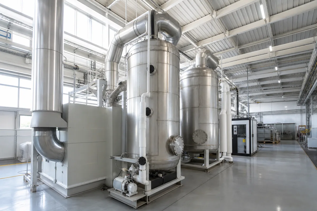
Solvent recovery normally uses activated carbon adsorption followed by steam, hot nitrogen or vacuum desorption. The desorbed solvent vapor is condensed, separated and collected. In printing plants, this method is most suitable when the solvent mix is simple and valuable.
Typical applications include:
- Gravure printing using toluene, ethyl acetate or MEK-rich solvent systems
- Lamination lines with high solvent consumption
- Plants with stable ink recipes and predictable production
- Facilities where recovered solvent can be reused after quality checking
A typical recovery system may include pre-filtration, cooling/dehumidification, activated carbon beds, desorption, condenser, separator, solvent storage tank and safety interlocks.
Important design ranges:
- Inlet VOC concentration: often 1,000–8,000 mg/m³, but depends on solvent LEL and system design
- Adsorption face velocity: commonly 0.2–0.6 m/s
- Carbon bed depth: often 600–1,200 mm
- Outlet temperature to carbon: usually kept below 40°C, because adsorption capacity drops at high temperature
- Relative humidity: lower is better; high humidity competes for adsorption sites
- Recovery efficiency: depends strongly on solvent mix, carbon selection and desorption method
The key question is not only “Can we recover solvent?” but “Can we reuse it safely and consistently?” Mixed solvents may form a recovered liquid with variable composition. If the printing process needs tight solvent ratios, recovered solvent may require distillation or controlled blending.
Advantages of recovery:
- Can reduce fresh solvent purchase volume
- Lower CO₂ generation than burning VOCs
- Good for high-value, reusable solvents
- Lower fuel use when VOC concentration is suitable
Limitations:
- More sensitive to solvent mixture and water content
- Requires solvent storage and handling
- Carbon beds need fire and temperature protection
- Not ideal for dirty exhaust with ink mist, resin particles or plasticizer vapors
- Recovered solvent quality must be managed
For safety, adsorption systems should be designed so inlet VOC concentration remains well below the lower explosive limit (LEL). A common operating rule is to keep normal operation below 25% LEL, with alarms and shutdown logic at defined higher levels. The exact limit depends on local rules, solvent type and risk assessment.
Solvent Destruction: Oxidizers and RTO Systems
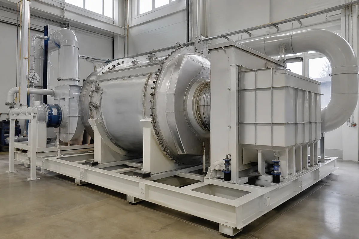
Solvent destruction converts VOCs into CO₂ and water by oxidation. For printing exhaust, common equipment includes direct-fired thermal oxidizers, catalytic oxidizers and RTOs. Among these, RTO systems are widely used for medium to large air flows because they recover heat through ceramic media.
Typical destruction temperatures:
| Technology | Typical Operating Temperature | Suitable VOC Concentration | Main Notes |
|---|---|---|---|
| Thermal oxidizer | 750–850°C | Medium to high | Simple concept, higher fuel use |
| Catalytic oxidizer | 250–450°C | Low to medium, clean gas | Catalyst can be poisoned by silicon, phosphorus, heavy metals |
| RTO | 760–850°C | Low to medium, large air flow | High heat recovery, common for printing ovens |
For RTO design, important parameters include:
- Air flow: often 10,000–200,000 m³/h per system, but larger systems are possible
- VOC concentration: commonly 300–3,000 mg/m³
- Heat recovery: often 90–95%, depending on chamber design and switching time
- Residence time in combustion zone: often around 0.5–1.0 seconds
- Pressure drop: commonly 2,500–4,500 Pa, depending on media and flow
A major advantage of RTO is that fuel consumption can become low when VOC concentration is high enough. The “self-sustaining” point depends on solvent heating value, inlet temperature, heat recovery and losses. As a rough rule, many solvent mixtures may allow autothermal operation around 1.5–2.5 g/m³ VOC in an RTO, but this number must be calculated for the actual gas.
Basic heat release estimate:
`text Heat release (kW) = VOC mass flow (kg/h) × LHV (kWh/kg) `
Many organic solvents have lower heating values around 6–10 kWh/kg. For example, 60 kg/h VOC at 8 kWh/kg gives:
`text 60 × 8 = 480 kW heat release `
Not all of this heat is useful. Some leaves with exhaust gas, some is lost through the shell, and some is used to heat incoming air. Still, this calculation helps compare recovery value and oxidation energy balance.
Advantages of destruction:
- Handles mixed solvents better than recovery
- No need to manage recovered solvent quality
- Suitable for low-value or contaminated solvent streams
- Can treat multiple lines together
- RTO is efficient for large air volumes
Limitations:
- Produces CO₂
- Requires high-temperature equipment and burner system
- Not suitable for streams containing high dust, tar or condensable oil without pretreatment
- Halogenated or sulfur-containing VOCs may form acid gases and require downstream scrubbing
- Explosion protection and LEL monitoring are essential
Direct Comparison for Printing Plants
The best choice is often clear after reviewing solvent value, exhaust concentration and production stability. The table below gives practical guidance.
| Factor | Solvent Recovery | Solvent Destruction |
|---|---|---|
| Best for | Valuable, reusable solvents | Mixed, low-value or dirty solvent vapors |
| Typical inlet VOC | 1,000–8,000 mg/m³ | 300–3,000 mg/m³ for many RTO cases |
| Exhaust air volume | Small to medium, concentrated streams | Medium to very large streams |
| Solvent mix | Simple and stable preferred | More tolerant of mixed VOCs |
| Energy use | Desorption energy, cooling load | Fuel use depends on VOC heat value |
| Product recovered | Liquid solvent | No solvent recovered |
| Pretreatment need | High: dust, mist and humidity control | High for dust, mist, resin and corrosive gases |
| Main safety issue | Carbon bed overheating, solvent storage | LEL control, burner and high temperature |
| Maintenance focus | Carbon condition, valves, condenser, tanks | Ceramic media, burners, valves, fans |
| Good fit | Gravure line with stable ethyl acetate/toluene use | Multi-line plant with variable ink and solvent recipes |
A simple decision rule:
- If VOC concentration is high, solvent is valuable, and recovered solvent can be reused, consider recovery first.
- If solvent mixture changes often, reuse is difficult, or exhaust comes from several different processes, destruction is usually simpler.
- If exhaust volume is very large but concentration is low, consider concentration + oxidation, such as zeolite rotor concentrator plus RTO.
- If the stream contains acid gas, alkaline gas, high humidity or particles, include proper pretreatment before either system.
In many real printing plants, a hybrid solution is also possible. For example, high-concentration oven exhaust may go to solvent recovery, while low-concentration room ventilation goes to a concentrator-RTO system. This avoids oversizing one system for all streams.
Design Details Often Overlooked
Many VOC systems fail not because the main technology is wrong, but because the inlet conditions are not controlled. Printing exhaust can contain ink mist, paper dust, adhesive vapor, plasticizer, and condensable resin. These materials can block carbon pores, foul heat exchangers, plug RTO ceramic media, or create fire risk.
Before selecting equipment, check these items:
- Actual air flow: measure normal and maximum values at operating temperature.
- VOC concentration profile: record low, average and peak concentrations. Do not rely only on one sample.
- Solvent list: include CAS numbers if available, flash point, LEL and approximate percentage.
- Temperature and humidity: adsorption capacity falls at high temperature and high humidity.
- Particles and mist: install filters, demisters or wet scrubbers where required.
- Corrosive components: chlorinated solvents, sulfur compounds or acid gases may require corrosion-resistant materials or scrubbing.
- Production schedule: 24-hour operation and one-shift operation have very different economics and thermal balance.
- Duct design: maintain suitable velocity, usually 10–18 m/s for VOC exhaust, depending on dust and condensable content.
- Fan material: PP, FRP, stainless steel or coated steel should be selected based on gas composition and temperature.
For wet pretreatment, PP scrubbers can remove water-soluble or corrosive components before VOC equipment, but they do not remove most non-polar solvents effectively. For example, a PP packed scrubber may be useful before an RTO if the gas contains acid mist, but it is not a substitute for activated carbon or oxidation when treating toluene or ethyl acetate vapor.
For activated carbon adsorbers, bed temperature monitoring is important. Multiple temperature probes across the bed are better than one probe at the outlet. For RTO systems, pay attention to valve sealing, purge time, ceramic media pressure drop and cold-start procedure.
Practical Next Step
To compare recovery and destruction correctly, prepare one data sheet for each exhaust source: air flow, temperature, humidity, solvent composition, VOC concentration range, operating hours and any dust or mist content. With these values, a supplier can calculate VOC mass flow, LEL margin, heat balance, bed size or oxidizer size, and recommend whether solvent recovery, RTO, catalytic oxidation or a hybrid system is the better fit for your printing plant VOC control project.