Start With the Exhaust Data
Activated carbon adsorber sizing should start from process data, not from the duct diameter. For solvent exhaust, the key question is: how much solvent mass must be captured before the carbon bed reaches its safe working capacity?
Collect these values first:
- Airflow rate: normally in m³/h or Nm³/h
- Solvent type: IPA, ethanol, acetone, toluene, xylene, MEK, ethyl acetate, mixed VOCs, etc.
- Inlet VOC concentration: mg/m³, ppmv, or %LEL
- Operating schedule: hours/day and days/week
- Temperature and humidity
- Dust, mist, or aerosol content
- Required outlet concentration or removal efficiency
- Whether the carbon is replaced, regenerated, or used as a polishing stage
For general industrial exhaust, activated carbon is usually applied when the solvent concentration is relatively low and stable. As a practical range, many fixed-bed carbon adsorbers work well at 50–2,000 mg/m³ total VOC. Higher concentrations can still be treated, but heat release, fire risk, and carbon consumption must be checked carefully.
If your solvent concentration is given in ppmv, convert it to mg/m³:
`text mg/m³ = ppmv × molecular weight / 24.45 `
This formula is valid at approximately 25°C and 1 atm. For other temperatures and pressures, correct the gas volume condition.
Example for toluene:
`text 100 ppmv toluene = 100 × 92.14 / 24.45 = 377 mg/m³ `
Then calculate the solvent mass loading:
`text Solvent mass per hour (kg/h) = airflow (m³/h) × VOC concentration (mg/m³) / 1,000,000 `
Example:
`text 10,000 m³/h × 500 mg/m³ / 1,000,000 = 5 kg/h VOC `
This value controls the carbon consumption rate and the replacement interval.
Estimate Carbon Working Capacity
Activated carbon does not use its full laboratory adsorption capacity in real equipment. For sizing, use working capacity, not maximum capacity. Working capacity depends strongly on solvent type, inlet concentration, humidity, temperature, and required outlet concentration.
As a rough engineering guide:
| Solvent type | Typical adsorption strength on activated carbon | Approximate working capacity by carbon weight* |
|---|---|---|
| Toluene, xylene, styrene | Strong | 15–30% |
| Ethyl acetate, butyl acetate | Medium to strong | 10–25% |
| MEK, MIBK | Medium | 8–18% |
| IPA, ethanol | Medium to weak, affected by humidity | 5–15% |
| Acetone | Weak to medium | 3–12% |
| Dichloromethane and some light chlorinated solvents | Application-specific | Often requires testing |
\*These are preliminary sizing ranges only. Final values should be checked against isotherm data, pilot testing, or supplier experience for the actual gas condition.
For conservative activated carbon adsorber sizing, many engineers use 10% working capacity as an initial estimate for mixed solvent exhaust. For difficult solvents such as acetone or humid alcohol exhaust, 5% may be safer. For aromatic solvents under dry conditions, 15–20% may be reasonable.
The required carbon mass is:
`text Carbon mass (kg) = total solvent to be adsorbed before changeout (kg) / working capacity `
Example:
- Airflow: 10,000 m³/h
- VOC concentration: 500 mg/m³
- VOC loading: 5 kg/h
- Operating time required before carbon replacement: 80 h
- Total VOC captured: 5 × 80 = 400 kg
- Assumed working capacity: 10%
`text Carbon mass = 400 / 0.10 = 4,000 kg `
This means the adsorber needs about 4 tonnes of activated carbon if the target changeout interval is 80 operating hours. If you want 160 hours, the carbon mass approximately doubles, assuming the same inlet conditions.
Size the Bed Area From Face Velocity
After estimating the carbon mass, size the bed cross-section using face velocity. If the velocity is too high, contact time is too short and pressure drop increases. If it is too low, the vessel becomes large and may have poor flow distribution unless designed correctly.
For fixed-bed activated carbon adsorbers treating solvent exhaust, common design ranges are:
- Superficial face velocity: 0.2–0.6 m/s
- Typical industrial starting point: 0.3–0.4 m/s
- Empty bed contact time (EBCT): 0.5–2.0 s for many VOC duties
- Carbon bulk density: 450–550 kg/m³ for many granular activated carbons
- Bed depth: usually 0.6–1.5 m per bed layer
Face velocity calculation:
`text Bed area (m²) = airflow (m³/s) / face velocity (m/s) `
For 10,000 m³/h:
`text 10,000 / 3,600 = 2.78 m³/s `
At 0.35 m/s:
`text Bed area = 2.78 / 0.35 = 7.94 m² `
So the adsorber needs about 8 m² of effective bed area. This could be arranged as one large bed, two parallel beds, or a vertical/horizontal configuration depending on footprint, access, and pressure drop.
Now check the bed volume from carbon mass:
`text Carbon volume (m³) = carbon mass (kg) / bulk density (kg/m³) `
Using 4,000 kg carbon and 500 kg/m³ bulk density:
`text Carbon volume = 4,000 / 500 = 8 m³ `
Bed depth:
`text Bed depth (m) = carbon volume (m³) / bed area (m²) `
`text Bed depth = 8 / 7.94 = 1.0 m `
This is a practical bed depth. The EBCT is:
`text EBCT (s) = bed volume (m³) / airflow (m³/s) `
`text EBCT = 8 / 2.78 = 2.9 s `
This is longer than many basic VOC applications and may be acceptable, but it also means a larger vessel. In this example, the carbon mass is driven by replacement interval, not by minimum contact time.
Check Pressure Drop, Humidity, and Safety
Activated carbon adsorber sizing is not finished until the operating risks are checked. Solvent exhaust is not only an adsorption problem; it is also a heat and safety problem.
Typical clean-bed pressure drops for granular carbon beds are often in the range of:
`text 800–1,500 Pa per metre of bed depth `
This depends on carbon particle size, bed depth, velocity, support screen, prefilter, and gas condition. Fine carbon gives better adsorption kinetics but higher pressure drop. Larger pellets reduce pressure drop but may reduce adsorption rate for some solvents.
Allow additional pressure drop for:
- Inlet and outlet plenums
- Mist eliminator or prefilter
- Duct transitions
- Dampers
- Safety screens or distributor plates
- Carbon dust screens
A complete system pressure drop of 1,500–3,000 Pa is common for many carbon adsorber installations, but the actual fan selection must be calculated for the full duct system.
Humidity is important. Water competes with many polar solvents and can reduce useful capacity. As a rule of thumb:
- Below 60% RH, most carbon adsorption duties are easier to predict.
- Above 70% RH, alcohols, ketones, and water-soluble VOCs may show reduced capacity.
- Condensed water or solvent mist should not enter the carbon bed.
Temperature also matters. Higher temperature reduces adsorption capacity. Many solvent carbon systems are designed for inlet temperatures below 40°C. If exhaust temperature is above this, cooling may be needed. Avoid operation near the solvent dew point because condensation inside the carbon bed can cause channeling, pressure drop increase, and local heating.
Safety checks are critical:
- Keep inlet VOC concentration well below the lower explosive limit. Many plants use 25% LEL or lower as an internal design limit, but the required limit depends on local regulation and plant safety rules.
- Avoid hot particles, sparks, and welding fumes entering the adsorber.
- Consider temperature sensors in the carbon bed for larger systems or higher solvent loading.
- Provide access doors for inspection and carbon removal.
- Use prefiltration when dust, oil mist, resin mist, or paint particles are present.
- Do not mix incompatible streams without checking reaction and heat release risks.
For high or fluctuating solvent concentration, a dilution fan, condenser, wet scrubber, zeolite rotor, regenerative thermal oxidizer, or hybrid VOC abatement system may be more suitable than a simple disposable carbon bed.
Choose the Equipment Arrangement
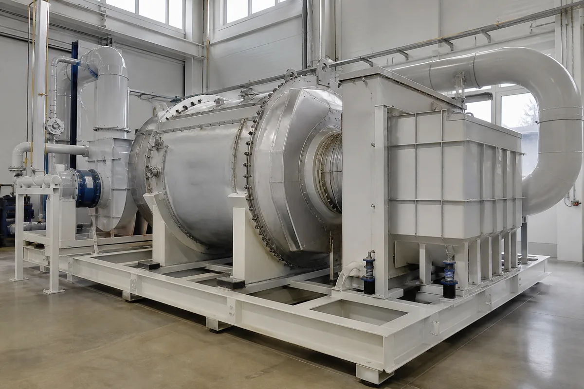
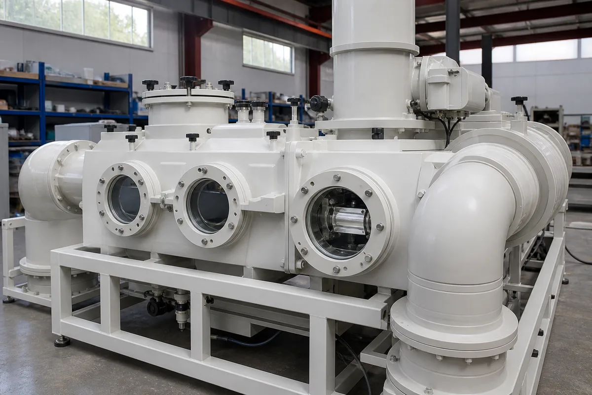
The physical arrangement affects maintenance as much as adsorption performance. For small airflows, a single carbon vessel with manual changeout may be acceptable. For continuous production, parallel adsorbers allow one bed to operate while another is isolated for carbon replacement.
Common configurations include:
| Arrangement | Typical use | Advantages | Limitations |
|---|---|---|---|
| Single fixed bed | Batch exhaust, intermittent operation | Simple layout, low control complexity | Shutdown needed for carbon replacement |
| Two beds in parallel | Continuous plant operation | One bed can be serviced while one operates | Requires valves and more footprint |
| Lead-lag beds in series | Higher outlet quality or breakthrough monitoring | Better protection against VOC slip | More pressure drop and equipment size |
| Tray-type carbon adsorber | Medium to large airflow | Easier carbon loading/unloading by layers | Needs good sealing and distribution |
| Vertical cylinder bed | Lower airflow or compact systems | Simple vessel fabrication | Bed area may limit high airflow |
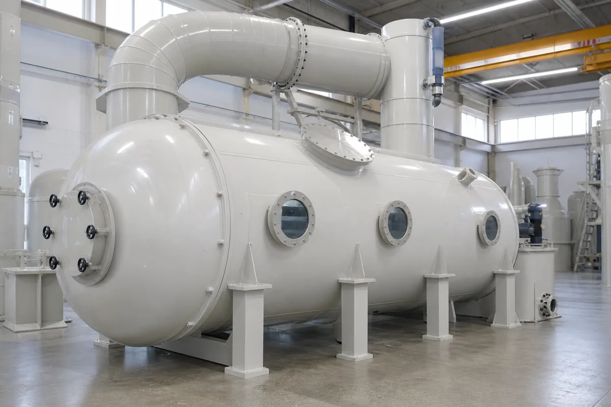
| Horizontal rectangular PP/steel-lined vessel | Corrosive or high airflow applications | Large bed area, lower velocity possible | Requires careful structural design |
For corrosive exhaust, the casing material should be selected according to gas composition. PP is often used for acidic or alkaline gas streams at moderate temperature, but solvent compatibility must be checked. Some organic solvents can soften or swell plastics. In those cases, stainless steel, coated steel, FRP, or a lined structure may be more suitable. The activated carbon, gasket, sealant, viewing window, and duct material should also be checked for compatibility.
For solvent exhaust containing acid gas, alkali gas, or water-soluble contaminants, a wet scrubber may be installed before the activated carbon adsorber. This can protect the carbon from inorganic loading. However, the scrubber outlet must include an effective mist eliminator, and the gas should not enter the carbon bed saturated with droplets.
Practical Next Step
For preliminary activated carbon adsorber sizing, prepare a simple data sheet with airflow, solvent list, concentration, temperature, humidity, operating hours, and required changeout interval. Then calculate VOC kg/h, assume a conservative working capacity, and check bed area by 0.3–0.4 m/s face velocity.
If you are unsure about mixed solvents, high humidity, or fire risk, send the full exhaust data to an equipment supplier for review before fixing the vessel size. The most useful information is not the duct diameter; it is the solvent mass loading and operating schedule.