Understand the HCl Fume Before Selecting the Scrubber
Hydrogen chloride gas is highly soluble in water. This is the main reason an hcl fume scrubber can often be simpler than scrubbers for chlorine, SO₂ or many VOCs. At 20°C, one volume of water can absorb hundreds of volumes of HCl gas, but real scrubber performance still depends on gas flow, inlet concentration, liquid distribution, packing depth, mist eliminator design and pH control.
Typical HCl fume sources include:
- Acid pickling tanks
- HCl storage tank vents
- Chemical mixing vessels
- Semiconductor and electronics processes
- Laboratory exhaust systems
- Waste gas from chlorination or hydrolysis processes
Before choosing water, caustic or a two-stage design, collect these basic data:
- Gas flow rate: normal and maximum, in m³/h or CFM
- Inlet HCl concentration: ppmv, mg/Nm³ or g/m³
- Gas temperature and moisture content
- Required outlet concentration
- Operation mode: continuous, batch or emergency vent
- Presence of other gases: HF, Cl₂, NH₃, solvent vapor, acid mist
- Available wastewater treatment method
A simple mass load calculation is useful:
`text HCl load (kg/h) = Gas flow (Nm³/h) × HCl concentration (mg/Nm³) ÷ 1,000,000 `
For example, if the exhaust flow is 5,000 Nm³/h and HCl is 2,000 mg/Nm³:
`text HCl load = 5,000 × 2,000 ÷ 1,000,000 = 10 kg/h `
This number is more important than concentration alone. A low concentration at high airflow may require a larger scrubber than a high concentration at low airflow.
Option 1: Water Scrubbing
For many HCl applications, water is the first choice. HCl dissolves in water and forms hydrochloric acid. No neutralizing chemical is consumed inside the scrubber, so operation is simple.
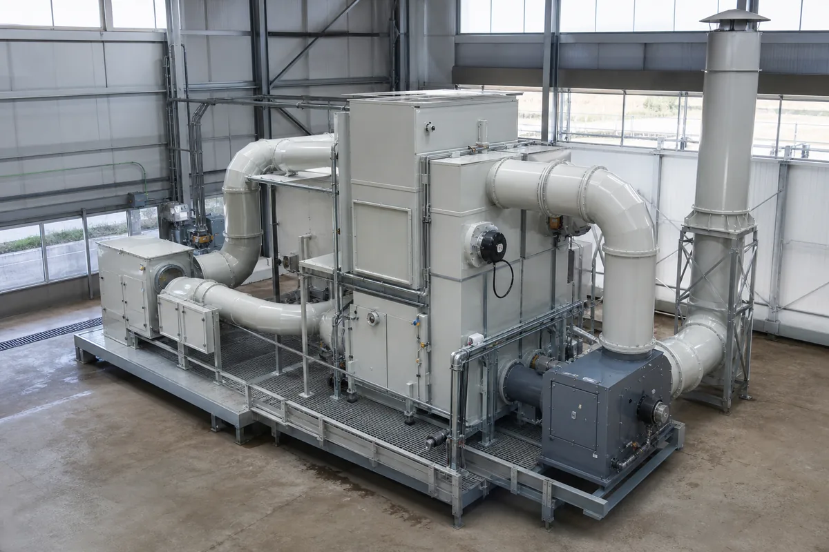
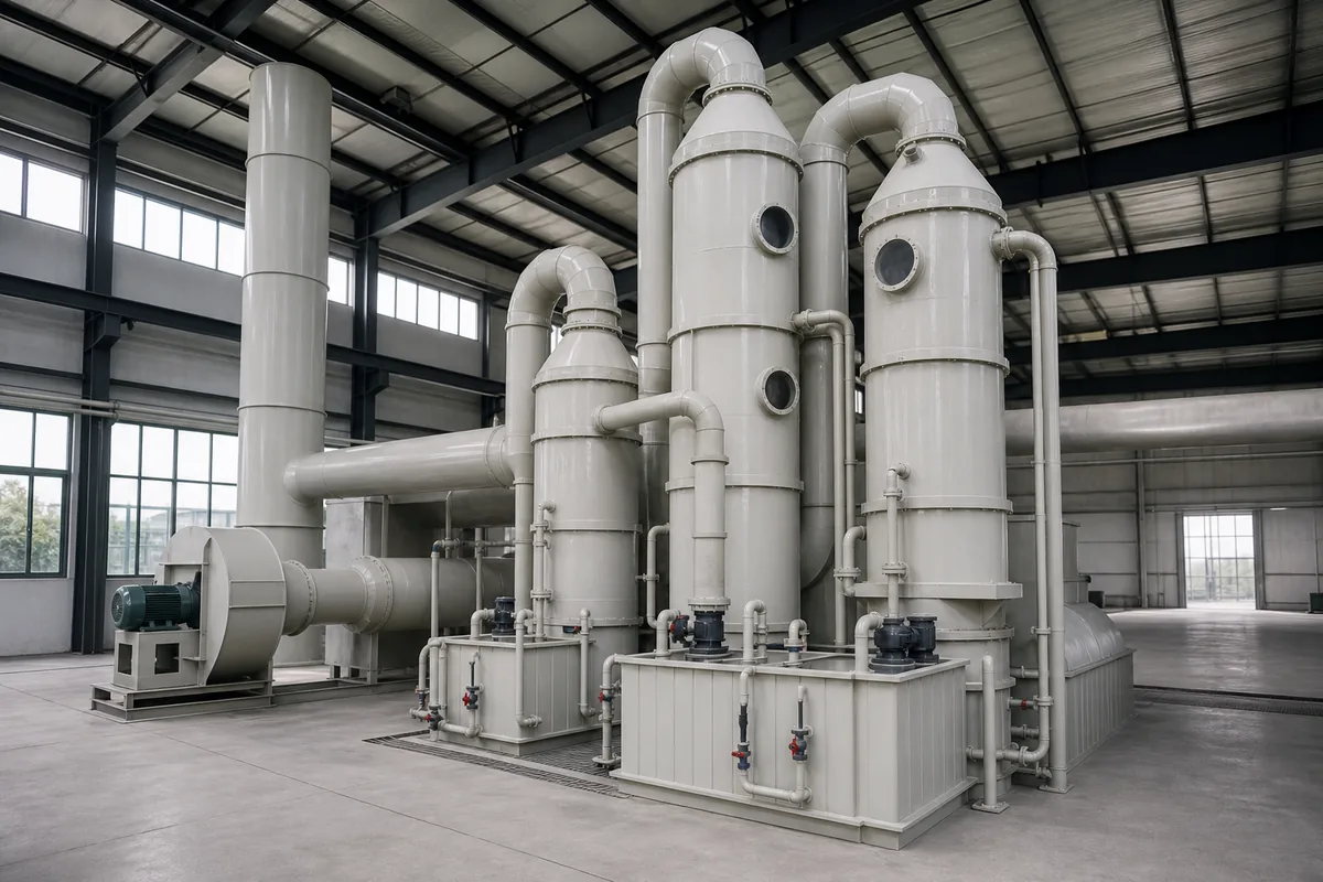
A typical packed tower water scrubber includes:
- PP or FRP tower body
- Spray headers and nozzles
- PP, PVC or PVDF packing
- Circulation tank
- Circulation pump
- Mist eliminator
- Make-up water and blowdown connections
- Optional pH and conductivity monitoring
For HCl fume, common design ranges are:
| Parameter | Typical Range | Notes |
|---|---|---|
| Empty tower gas velocity | 1.0–2.0 m/s | Lower velocity reduces pressure drop and mist carryover |
| Packing height | 1.0–2.5 m | Depends on inlet load and outlet target |
| Liquid-to-gas ratio | 1.5–4.0 L/m³ gas | Higher for high concentration or hot gas |
| Pressure drop | 800–1800 Pa | Depends on packing type and gas velocity |
| Circulation liquid pH | Often below 2 | It becomes hydrochloric acid |
| Removal efficiency | Often 90–99%+ | Depends on design and operating conditions |
Water scrubbing is usually suitable when:
- Outlet requirement is not extremely low
- Waste acid can be reused, recovered or treated
- Inlet HCl concentration is moderate to high
- There is little risk from acidic wastewater
- The process can accept low-pH circulation liquid
One important point: as HCl dissolves, the scrubbing liquid becomes hydrochloric acid. This reduces the absorption driving force compared with clean water. Therefore, blowdown and make-up water are necessary. Conductivity control is often more stable than pH control in strong acid service because the pH may remain very low over a wide acid concentration range.
A practical rule of thumb is to limit the acid concentration in the circulation tank if high removal is required. For many general fume systems, operators keep hydrochloric acid below about 5–10 wt%, but the correct limit depends on outlet emission requirement and corrosion material selection.
For construction, PP is widely used for HCl fume scrubbers at normal temperatures. In many plants, PP is suitable below about 80°C, but actual allowable temperature depends on wall thickness, structural design and chemical concentration. For hotter gas, pre-cooling or other materials may be needed.
Option 2: Caustic Scrubbing
Caustic scrubbing uses sodium hydroxide solution to neutralize HCl:
`text HCl + NaOH → NaCl + H₂O `
The main advantage is that caustic maintains high absorption capacity by keeping the liquid alkaline or near neutral. This can help achieve lower outlet HCl levels, especially for dilute exhaust where the final polishing step is important.
Typical operating ranges for caustic HCl scrubbing are:
- Circulation pH: 8–10 for many systems
- NaOH concentration in dosing tank: commonly 10–30 wt%
- Scrubber liquid pH alarm: often low alarm at pH 7–8
- ORP control: usually not needed for HCl alone
- Liquid-to-gas ratio: commonly 1.5–5.0 L/m³ gas
- Packing height: commonly 1.2–3.0 m
Theoretical caustic consumption can be calculated from molecular weight:
`text 36.46 kg HCl reacts with 40.00 kg NaOH NaOH required = HCl load × 40.00 ÷ 36.46 NaOH required ≈ HCl load × 1.10 `
If the HCl load is 10 kg/h:
`text 100% NaOH required ≈ 10 × 1.10 = 11 kg/h `
If using 30 wt% NaOH solution:
`text 30% NaOH solution required ≈ 11 ÷ 0.30 = 36.7 kg/h `
In real operation, add a safety factor. A typical dosing design may use 10–30% extra capacity depending on pH control stability and load fluctuation.
Caustic scrubbing is usually suitable when:
- Very low outlet HCl is required
- HCl load changes quickly
- Wastewater treatment is designed for salt solution
- There is no useful recovery route for weak hydrochloric acid
- The plant wants automatic pH-controlled operation
However, caustic is not always better. It creates sodium chloride wastewater. At high HCl load, salt concentration can rise quickly, increasing blowdown requirements. High dissolved salt may cause scaling, pump seal issues or nozzle plugging if not controlled.
Also, strong caustic dosing into an acidic scrubber tank is exothermic. Good mixing and correct dosing point design are important. Do not inject concentrated NaOH directly onto PP walls or pump suction without dilution and mixing, because local heat and chemical attack may shorten equipment life.
When a Two-Stage HCl Fume Scrubber Makes Sense
A two-stage design normally means the first stage uses water and the second stage uses caustic. The first stage absorbs most of the HCl and produces acidic blowdown. The second stage polishes the remaining HCl with pH-controlled alkaline liquid.
This arrangement is useful when HCl load is high and outlet requirement is strict. The water stage reduces caustic consumption because much of the HCl is removed without neutralization. The caustic stage then handles the final low-concentration polishing.
A two-stage system can be built as:
- Two separate packed towers in series
- One vertical tower with two packed beds and two liquid circuits
- One horizontal scrubber with two spray/packing zones, for special layout needs
Separate liquid circuits are important. If the acidic first-stage liquid and alkaline second-stage liquid mix freely, the benefit is lost.
Comparison of the three common choices:
| Scrubber arrangement | Best use | Advantages | Limitations |
|---|---|---|---|
| Water only | Moderate outlet target; acid reuse or simple wastewater treatment | Low chemical use, simple operation, good for high HCl solubility | Outlet may be limited by acid concentration in liquid; low-pH wastewater |
| Caustic only | Low outlet target; moderate HCl load | Strong absorption driving force, easy pH control | Continuous NaOH use; salt wastewater; dosing system required |
| Water + caustic two-stage | High HCl load and strict outlet target | Reduces caustic use, stable final polishing, flexible control | Higher equipment size, two liquid circuits, more instruments |
As a rough engineering approach:
- Use water only when the required removal efficiency is around 90–98% and acidic effluent can be handled.
- Use caustic only when the HCl load is not large but the outlet target is low.
- Use two-stage when removal above 99% is needed, especially with high inlet HCl concentration or variable batches.
These are rules of thumb, not guarantees. Final design should be checked using mass transfer assumptions, packing data and the required emission limit.
Design and Operation Points That Affect Performance
Many HCl scrubber problems are not caused by the chemistry. They are caused by poor gas-liquid contact, mist carryover or unstable control.
Key points to check during design:
- Gas velocity
For vertical packed towers, 1.0–2.0 m/s empty tower velocity is common. Higher velocity reduces tower diameter but increases pressure drop and entrainment risk.
- Packing selection
PP Pall rings, Tellerette packing and other random packing are commonly used. Smaller packing gives more surface area but higher pressure drop and higher plugging risk. For dirty gas, avoid very small packing.
- Liquid distribution
Uneven spray distribution causes channeling. The nozzle layout should wet the full packing cross-section. Access ports are useful for inspection and cleaning.
- Mist eliminator
HCl systems often generate acid mist. A chevron or mesh mist eliminator is normally installed at the outlet. Face velocity is often kept around 2–3 m/s, depending on eliminator type.
- Materials
PP is common for HCl fume at ambient to moderate temperature. For fans, PP or FRP housings with corrosion-resistant impellers are often used. Fasteners, supports, pump wetted parts and instruments must also suit acid or caustic conditions.
- Control system
Water scrubbers may use conductivity and tank level control. Caustic stages normally use pH control with automatic NaOH dosing. The pH probe should be installed where liquid is well mixed and easy to maintain.
- Blowdown rate
Blowdown prevents excessive acid or salt build-up. The required rate depends on HCl load, target liquid concentration and make-up water quality.
A simple steady-state estimate for water scrubber blowdown is:
`text Blowdown (kg/h) = HCl absorbed (kg/h) ÷ Target HCl mass fraction `
If 9 kg/h HCl is absorbed and the target acid concentration is 5 wt%:
`text Blowdown ≈ 9 ÷ 0.05 = 180 kg/h `
This is only a first estimate. Evaporation, water make-up, density and other dissolved materials should be considered for detailed design.
Practical Next Step
To choose between water, caustic and two-stage scrubbing, prepare one design sheet with gas flow, HCl concentration, temperature, outlet target and wastewater limits. Then calculate the HCl load in kg/h. If the load is high and the outlet target is strict, evaluate a two-stage hcl fume scrubber early, not after the layout is fixed. This avoids undersized towers, excessive caustic use and difficult wastewater operation.