Why the Recirculation System Deserves a Separate Specification
In many scrubber enquiries, the buyer specifies the tower diameter, packing height, mist eliminator and fan airflow, but only writes “with circulation pump and tank” for the liquid side. This is risky. The scrubber recirculation system controls liquid distribution, chemical contact, pH stability, scaling risk and pump life. A good tower with a weak recirculation system will still perform poorly.
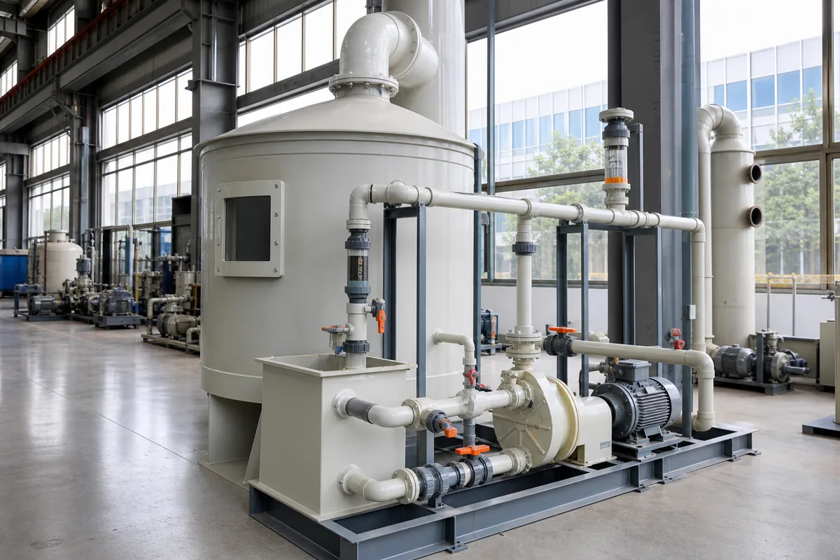
For a typical packed-bed PP wet scrubber, the recirculation system includes:
- Recirculation tank or sump
- Circulation pump
- Suction and discharge piping
- Spray header and nozzles
- Strainer or filter
- Level control
- Chemical dosing points
- Blowdown and overflow connections
- Drain and inspection ports
- Instruments such as pH, ORP, conductivity, flow and pressure gauges
The main engineering question is simple: can the system deliver the required liquid flow to the packing, continuously, without cavitation, blockage or unstable chemistry?
A practical specification should define at least:
`text Gas flow rate Target pollutants and inlet concentration Required liquid-to-gas ratio Recirculation flow rate Tank working volume Pump flow and head Pipe diameter and material Nozzle type and quantity Control points and instruments Blowdown method `
If these are not agreed before fabrication, the final design may still “look complete” but be difficult to operate.
Size the Recirculation Flow Before Selecting the Pump
The first number to calculate is the recirculation liquid flow. For packed scrubbers, a common design method is the liquid-to-gas ratio, usually written as L/G.
Typical starting ranges are:
| Application | Typical L/G Range | Notes |
|---|---|---|
| Acid gas absorption, such as HCl or HF | 2–6 L/m³ gas | Higher for high inlet concentration or high removal target |
| Alkali gas absorption, such as NH₃ | 3–8 L/m³ gas | Often requires acid dosing and good pH control |
| Odor or low-concentration soluble gases | 1.5–4 L/m³ gas | Depends strongly on gas solubility |
| Dust plus soluble gas | 4–10 L/m³ gas | Higher liquid rate helps washing, but increases wastewater |
| Cooling or humidification duty | 5–15 L/m³ gas | Heat load controls the water rate |
Use the actual gas flow at operating temperature and moisture content when possible. For preliminary sizing:
`text Recirculation flow QL = Gas flow QG × L/G `
Example:
`text Gas flow QG = 20,000 m³/h Selected L/G = 4 L/m³ QL = 20,000 × 4 = 80,000 L/h = 80 m³/h `
This 80 m³/h is the flow that must reach the spray system, not only the pump nameplate flow. Pipe losses, nozzle pressure and fouling margin must be considered.
For many packed towers, spray nozzle operating pressure is commonly 0.05–0.20 MPa at the nozzle inlet, depending on nozzle type and droplet requirement. Large free-passage spiral nozzles may work at lower pressure. Fine atomizing nozzles need cleaner liquid and higher pressure. In dirty or scaling service, avoid small orifices unless filtration is reliable.
Also check the minimum wetting rate of the packing. Random plastic packing often needs a minimum irrigation rate around 5–10 m³/m²·h to avoid dry areas, depending on packing size and surface. The tower cross-sectional area is:
`text Area A = π × D² / 4 Irrigation rate = QL / A `
If the irrigation rate is too low, gas may pass through poorly wetted packing and removal efficiency drops.
Specify Tank Volume, Levels and Blowdown
The recirculation tank is not only a container. It provides pump suction stability, chemical mixing volume, solids settling space and operating buffer. A common rule of thumb is to provide 3–10 minutes of recirculation flow as working volume.
`text Working volume = Recirculation flow × retention time `
Example:
`text Recirculation flow = 80 m³/h Retention time = 5 minutes = 5/60 h Working volume = 80 × 5/60 = 6.7 m³ `
For strong pH reaction, variable gas load, or manual chemical dosing, choose a longer retention time. For compact packaged scrubbers with stable low load, shorter retention time may be acceptable, but pump suction must still be protected.
When specifying a PP tank or integrated sump, define:
- Normal liquid level: operating level during recirculation.
- Low-low level: stops pump to prevent dry running.
- High level: alarms before overflow.
- Overflow size and destination: never leave this unclear.
- Drain size: large enough for sludge and maintenance cleaning.
- Manhole or access cover: needed for inspection and cleaning.
- Make-up water connection: automatic valve or manual valve.
- Blowdown connection: manual or automatic.
Blowdown is often forgotten. In a wet scrubber, dissolved salts increase over time. If the scrubber neutralizes acid gas with caustic soda, sodium salts accumulate. Conductivity control is commonly used. The correct blowdown rate depends on inlet loading, chemical dose and allowable dissolved solids, but a simple mass balance should be made.
For preliminary discussion, include:
`text Continuous blowdown or batch blowdown Expected wastewater pH range Expected solids or salt loading Neutralization requirement before discharge `
Do not rely on overflow as the normal blowdown method. Overflow is for abnormal high level, not process control.
Pump and Piping: Use Real Operating Head, Not Guesswork
A circulation pump should be selected at the required flow and total dynamic head, with a margin. Do not select only by motor power. The total head includes static lift, pipe friction, fittings, valves, spray header loss and nozzle pressure.
A simplified calculation is:
`text Pump head = Static head + Pipe friction + Fitting losses + Nozzle required pressure head + Margin `
Pressure head conversion:
`text 10 m water head ≈ 0.1 MPa ≈ 1 bar `
Example:
`text Static height to spray header = 5 m Pipe and fitting losses = 6 m Nozzle pressure requirement = 10 m Margin = 3 m Required pump head = 24 m `
So the pump duty should be around 80 m³/h at 24 m head, not simply “80 m³/h pump”.
For corrosive scrubber liquid, common pump materials include FRP, PP, PVDF or lined pumps. PP pumps are often suitable for many acid and alkali services at moderate temperature, but the chemical concentration and temperature must be checked. For oxidizing chemicals, solvents or high temperature, material selection may change.
Pipe velocity is another important point. Too small a pipe wastes pump energy and increases erosion or scaling. Too large a pipe may allow solids to settle.
Practical velocity ranges:
- Pump suction pipe: 0.8–1.5 m/s
- Pump discharge pipe: 1.5–2.5 m/s
- Slurry or dirty liquid: keep enough velocity to reduce settling, often above 1.2 m/s, depending on solids
- Chemical dosing line: depends on dosing pump flow; use small tubing but protect from blockage
Pipe inside diameter can be estimated from:
`text D = √(4Q / πv) `
Where:
D= inside diameter, mQ= flow, m³/sv= velocity, m/s
For 80 m³/h:
`text Q = 80 / 3600 = 0.0222 m³/s If discharge velocity v = 2.0 m/s D = √(4 × 0.0222 / 3.1416 / 2.0) = 0.119 m `
A DN125 discharge pipe is therefore a reasonable starting point, subject to actual pipe ID and layout.
For the suction line, use a larger diameter if possible, minimize elbows, and install the pump below or near the liquid level. Poor suction design causes cavitation, vibration, low flow and seal failure. A foot valve is not a substitute for good suction layout.
Details That Prevent Daily Maintenance Problems
Small details often decide whether the scrubber is easy or painful to operate. During procurement, ask the supplier to show the recirculation system on a P&ID or at least a clear piping sketch.
Important details include:
- Strainer position: Install before the pump if nozzles may block, but make it easy to clean. A clogged suction strainer can cause cavitation.
- Pressure gauge: Install on pump discharge. A rising pressure may mean nozzle blockage. A falling pressure may mean pump wear, low level or broken piping.
- Flow indication: A rotameter or magnetic flowmeter helps operators confirm actual liquid rate. For large systems, flow indication is strongly recommended.
- Spray header access: Nozzles should be removable from manholes or external flanges.
- Nozzle free passage: For dirty liquid, use large free-passage nozzles. Small full-cone nozzles can block easily.
- Chemical injection point: Dose into a turbulent zone, not directly at the pump seal. Strong local chemical concentration can damage materials.
- Anti-vortex design: Use enough submergence or a baffle near pump suction.
- Flexible connection: Useful at pump inlet and outlet to reduce vibration transfer, if compatible with the chemical.
- Drain slope: Piping should not trap liquid where crystallization or freezing is possible.
- Spare nozzle and gasket set: Small spares reduce downtime.
For outdoor installations, consider freezing. PP piping and tanks can crack if water freezes inside. Options include heat tracing, insulation, drain-down design or indoor installation. The correct choice depends on local winter temperature and operating schedule.
For hot gas service, also check recirculation liquid temperature. PP is widely used for corrosion-resistant scrubbers, but its allowable strength decreases as temperature increases. The exact limit depends on material grade, wall thickness, stress and chemical. If continuous liquid temperature may exceed about 70–80°C, confirm the design carefully and consider alternative materials or cooling.
Practical Next Step: Send a Liquid-Side Data Sheet
Before ordering a wet scrubber, prepare a short data sheet for the scrubber recirculation system. Include gas flow, pollutants, expected concentration, required removal efficiency, liquid chemicals, operating temperature, available power supply, wastewater limits and preferred instruments.
At minimum, ask the supplier to confirm these six numbers in writing:
`text Recirculation flow rate Tank working volume Pump flow and head Pipe diameters Nozzle quantity and pressure Blowdown method `
If these values are clear, the scrubber will be easier to operate, easier to maintain and more predictable in performance.