Why pH Control Is the Center of Scrubber Operation
In a recirculating wet scrubber, the liquid is not only water. It is a working chemical solution. The pH tells you whether this solution still has enough alkalinity or acidity to absorb the target gas. Poor scrubber pH control is one of the most common reasons for unstable removal efficiency, scaling, corrosion, high chemical use, and strong odor at the stack.
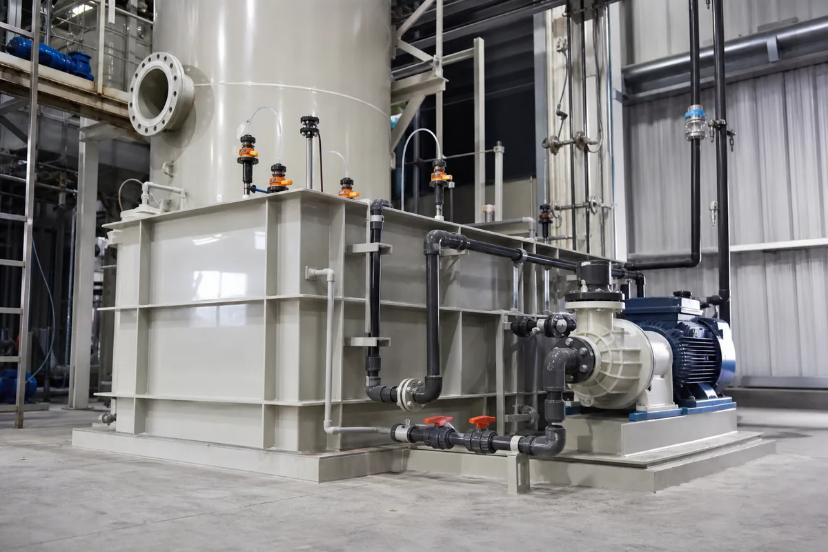
Most industrial recirculating scrubbers use a sump or circulation tank. The pump sends liquid to spray nozzles or packing. Gas contacts the liquid, pollutants transfer into the liquid, and the liquid returns to the sump. During this cycle:
- Acid gases such as HCl, HF, SO₂, H₂S, or Cl₂ consume alkali.
- Alkaline gases such as NH₃ consume acid.
- Dissolved salts increase over time.
- Evaporation concentrates the liquid.
- Fresh make-up water dilutes the sump.
- Bleed-off removes accumulated salts and suspended solids.
A good control system must manage all three: chemical dosing, bleed, and make-up water. If only pH is controlled and bleed is ignored, the scrubber may show correct pH but still fail because of high dissolved solids, blocked nozzles, or packed-bed scaling.
Selecting the pH Setpoint
The correct pH setpoint depends on the pollutant, required outlet concentration, scrubbing chemistry, and material compatibility. Do not use one universal pH value for all scrubbers.
Typical operating ranges are:
| Application | Common dosing chemical | Typical pH range | Notes |
|---|---|---|---|
| HCl / HF acid gas removal | NaOH, Na₂CO₃, lime slurry | 8.5–10.5 | Higher pH improves absorption, but may increase scaling risk |
| SO₂ removal | NaOH, lime, magnesium hydroxide | 6.5–9.0 | Depends strongly on reagent and oxidation conditions |
| H₂S caustic scrubbing | NaOH, often with oxidant | 9.0–11.5 | High pH keeps sulfide in liquid phase |
| Chlorine gas scrubbing | NaOH + reducing agent if needed | 9.0–11.0 | ORP control may also be required |
| Ammonia scrubbing | H₂SO₄, HCl, citric acid | 3.0–6.0 | Lower pH improves NH₃ capture, but affects material selection |
| General odor polishing | NaOH, acid, oxidant depending on gas | Application-specific | Often requires both pH and ORP control |
For PP scrubbers, the vessel body is normally suitable for many acidic and alkaline recirculation liquids at moderate temperature, but gaskets, pumps, instruments, and mist eliminator materials must also match the solution. Temperature is important. Many PP systems are designed for gas and liquid temperatures below about 70–80°C, but the real limit depends on mechanical stress, thickness, and chemical concentration.
As a rule of thumb, do not control exactly at the edge of the useful range. If the process needs pH above 9.0, a setpoint of 9.5 with a deadband of ±0.2 to ±0.3 pH is usually more stable than trying to hold exactly 9.00.
Chemical Dosing: Size the System Before Tuning It
A pH controller cannot fix an undersized dosing pump. Start by estimating the pollutant loading and chemical demand.
For acid gas neutralization with sodium hydroxide:
`text HCl + NaOH → NaCl + H₂O `
Molar ratio is 1:1.
Example:
- Gas flow: 10,000 m³/h
- HCl inlet concentration: 300 mg/m³
- HCl mass load = 10,000 × 300 / 1,000,000 = 3.0 kg/h
- Molecular weight HCl = 36.46
- Moles HCl = 3.0 / 36.46 = 0.0823 kmol/h
- NaOH required = 0.0823 × 40.0 = 3.29 kg/h
- Add safety factor 1.2–1.5 for control response and process variation
Design NaOH demand = 4.0–5.0 kg/h as 100% NaOH
If using 30% NaOH solution:
`text Solution flow = NaOH mass / concentration = 5.0 / 0.30 = 16.7 kg/h `
At density about 1.33 kg/L, this is:
`text 16.7 / 1.33 = 12.6 L/h `
So the dosing pump should not be 0–10 L/h. A better selection may be 0–25 L/h or 0–30 L/h, depending on turndown.
Practical dosing rules:
- Use a dosing pump with adjustable stroke or VFD control.
- Keep normal operation at 30–70% of pump capacity.
- Install an injection quill or dosing point in a high-mixing area, normally the circulation line or sump near pump suction, not directly beside the pH probe.
- Provide a non-return valve to stop scrubber liquid entering the chemical line.
- Use compatible tubing: for NaOH, PE, PTFE, PVC, or PP are common; for acids, check concentration and temperature.
- For concentrated NaOH, protect against crystallization in cold climates.
For strong acids and caustic, avoid on/off dosing if the sump volume is small. It causes pH overshoot. Proportional dosing or pulse-width control gives smoother operation.
A useful sizing check is the sump turnover time:
`text Turnover time = sump working volume / circulation flow `
If the sump is 2 m³ and circulation flow is 60 m³/h:
`text 2 / 60 = 0.033 h = 2 minutes `
This is good for fast mixing. If turnover time is above 5–10 minutes, pH response will be slow and control tuning must be conservative.
Bleed-Off and Make-Up: Controlling What pH Cannot See
pH measures hydrogen ion activity. It does not measure total dissolved solids, chloride, sulfate, sodium salts, suspended solids, or hardness. In many scrubbers, the liquid can have correct pH but excessive salt concentration.
Bleed-off removes contaminated liquid. Make-up water replaces the lost volume. Bleed rate is normally controlled by one of these methods:
- Continuous bleed: simple and stable, suitable for constant loads.
- Timed bleed: opens a valve for a set time every hour or shift.
- Conductivity-based bleed: common for salt control.
- Manual batch drain: acceptable only for small or low-duty systems.
For acid gas scrubbers using NaOH, conductivity is often a useful indirect indicator of salt build-up. Typical conductivity limits may range from 20 to 100 mS/cm, depending on pollutant, water quality, pump material, scaling risk, and disposal limit. There is no universal value.
A simple mass balance helps estimate the minimum bleed rate:
`text Bleed rate = salt formation rate / allowable salt concentration `
Example:
From the HCl example above:
- HCl load = 3.0 kg/h
- NaCl formed from HCl:
- Moles HCl = 0.0823 kmol/h
- NaCl MW = 58.44
- NaCl = 0.0823 × 58.44 = 4.81 kg/h
If allowable NaCl concentration in sump is 80 kg/m³:
`text Bleed = 4.81 / 80 = 0.060 m³/h `
That is 60 L/h minimum, not including evaporation, other salts, suspended solids, or safety margin. A practical design may use 80–120 L/h adjustable bleed for this case.
Make-up water must cover:
`text Make-up = bleed + evaporation + drift + liquid discharged with sludge `
Evaporation depends on gas temperature, humidity, and scrubber heat load. In cool low-temperature gas service, it may be small. In hot gas quench service, evaporation can dominate the water balance.
For packed-bed PP scrubbers, stable sump level is important. Low level causes pump cavitation and nozzle pressure loss. High level can flood duct connections or entrain liquid. Use a level switch or level transmitter with:
- Low-low level pump trip
- Low level make-up start
- High level alarm
- Overflow or emergency drain where appropriate
Make-up water quality also matters. Hard water combined with high pH can form calcium carbonate scale. If the water hardness is high and the scrubber runs above pH 9, consider softened water, lower cycles of concentration, or anti-scaling measures.
Instruments, Installation, and Control Logic
Many scrubber pH problems are instrument problems, not chemistry problems. A pH probe installed in the wrong place will create false dosing.
Good practice:
- Install the pH probe in a well-mixed sump zone or side-stream sample chamber.
- Avoid dead corners, chemical injection points, and zones with air bubbles.
- Keep probe tip always submerged.
- Provide isolation valves if using a side-stream chamber.
- Clean the probe regularly; frequency may be weekly to monthly depending on fouling.
- Calibrate with pH 4, 7, and/or 10 buffers according to operating range.
- Replace probes when response becomes slow or offset cannot be corrected.
For alkaline scrubbers, two-point calibration at pH 7 and 10 is common. For acidic ammonia scrubbers, use pH 4 and 7.
Basic control logic for caustic dosing:
`text If pH < setpoint - deadband: start or increase alkali dosing If pH > setpoint + deadband: stop or reduce alkali dosing `
For acid dosing, the logic is opposite.
For small systems, on/off dosing with a deadband may be enough. For larger scrubbers, use PID or proportional control. However, aggressive PID tuning causes overshoot because pH response is nonlinear. Near neutral pH, small chemical addition can cause a large pH change. At high alkalinity, response is slower.
Suggested starting values for many recirculating systems:
- Deadband: 0.2–0.3 pH
- Minimum dosing delay after pump start/stop: 30–120 seconds
- pH alarm delay: 60–180 seconds
- High-high and low-low pH alarms: typically 1.0–1.5 pH units from setpoint, depending on process risk
If oxidants are used, such as sodium hypochlorite for odor or sulfide oxidation, do not rely only on pH. Add ORP control where required. pH and ORP interact; for example, hypochlorite chemistry changes strongly with pH.
Commissioning and Daily Operation Checklist
During commissioning, do not start with automatic control immediately. First fill the sump, start circulation, check spray pattern and pressure, then dose slowly in manual mode until near the target pH. After mixing is confirmed, switch to automatic.
Record these operating values during the first days:
- Gas flow rate and inlet pollutant concentration if available
- Sump pH trend
- Chemical consumption per hour or per day
- Conductivity
- Sump level and make-up water use
- Bleed valve opening or bleed flow
- Pump pressure and nozzle condition
- Visible mist carryover or packing fouling
Compare actual chemical use with theoretical demand. If actual NaOH use is two or three times higher than calculated, possible reasons include higher inlet load, CO₂ absorption, poor gas-liquid contact, wrong concentration chemical, pH probe error, or excessive blowdown.
Common symptoms and checks:
| Symptom | Possible cause | First check |
|---|---|---|
| pH drops quickly | Dosing pump too small, high inlet load, empty chemical tank | Chemical tank level and pump output |
| pH overshoots | Poor mixing, dosing too close to probe, controller too aggressive | Probe location and dosing delay |
| Correct pH but poor removal | Low liquid flow, blocked nozzles, gas bypass, high salt | Pump pressure, packing, conductivity |
| Scale in packing | Hard make-up water, high pH, low bleed | Hardness, conductivity, bleed rate |
| Pump cavitation | Low sump level, blocked suction strainer | Level controls and suction line |
| High water use | Bleed set too high, leaking drain valve, high evaporation | Bleed flow and temperature |
Practical Next Step
For an existing scrubber, collect one week of pH, conductivity, chemical use, bleed volume, make-up volume, and gas load data. Then calculate the theoretical chemical demand and salt formation rate. This will show whether the problem is dosing capacity, bleed control, water quality, or instrumentation. For a new scrubber, provide these same design values to the equipment supplier so the sump volume, dosing pump, bleed valve, and control logic can be sized correctly.