Why LEL Control Is Needed in VOC Abatement
In a VOC exhaust system, the main safety question is simple: can the solvent vapour concentration enter the flammable range? If yes, the system needs a practical control method. For many factories, this means LEL monitoring VOC system design with dilution air, shutdown interlocks, and clear operating limits.
LEL means Lower Explosive Limit. It is the lowest concentration of vapour in air that can ignite if an ignition source is present. For example, typical LEL values in air are:
| Solvent / VOC | Approximate LEL by volume | Notes |
|---|---|---|
| Toluene | 1.1% v/v | Common in coating and printing |
| Xylene | 1.0% v/v | Often mixed isomers |
| Ethyl acetate | 2.0% v/v | Common in laminating and coating |
| Acetone | 2.5% v/v | High vapour pressure |
| Ethanol | 3.3% v/v | Water miscible |
| IPA | 2.0% v/v | Common cleaning solvent |
The control target is not 100% LEL. In industrial ventilation, alarm and interlock points are normally set much lower. A common engineering practice is:
- Normal operation: below 10% LEL
- Pre-alarm: 10–20% LEL
- High alarm / action: 20–25% LEL
- Emergency shutdown or full dilution: 40–50% LEL, depending on risk assessment and local requirements
The exact values depend on solvent type, process stability, sensor position, equipment design, and site safety rules. For adsorption systems using activated carbon, lower operating concentrations are often preferred because carbon beds can heat up when adsorbing high VOC loads.
Estimate VOC Concentration Before Selecting Instruments
Before choosing the LEL monitor, estimate the possible VOC concentration in the duct. The basic formula is:
`text VOC concentration (ppmv) = VOC vapour flow (m³/h) / exhaust air flow (m³/h) × 1,000,000 `
If the solvent evaporation rate is known by mass:
`text VOC vapour flow (m³/h) = mass evaporation rate (kg/h) × 24.45 / molecular weight `
This formula uses 24.45 m³/kmol at about 25°C and 1 atm. For a rough design check, it is acceptable. For high-temperature exhaust or pressure differences, correct the gas volume.
Example:
A coating line evaporates 8 kg/h of toluene. Molecular weight of toluene is 92.1 kg/kmol. Exhaust air flow is 8,000 m³/h.
`text VOC vapour flow = 8 × 24.45 / 92.1 = 2.12 m³/h
Concentration = 2.12 / 8,000 × 1,000,000 = 265 ppmv `
Toluene LEL is about 1.1% v/v, or 11,000 ppmv.
`text %LEL = 265 / 11,000 × 100 = 2.4% LEL `
This looks safe under normal average conditions. But you must still check abnormal cases:
- Batch charging or cleaning with open solvent containers
- Short-time high evaporation when ovens heat up
- Exhaust fan speed reduction
- Damper closed or filter blocked
- Wrong solvent used by operators
- Production rate increase
- Adsorber desorption or regeneration gas recirculation
For mixtures, use a conservative method. If the VOC composition is known, apply Le Chatelier’s formula:
`text 1 / LELmix = y1 / LEL1 + y2 / LEL2 + y3 / LEL3 ... `
Where y is the volume fraction of each solvent in the VOC mixture, not in total air.
If the solvent mixture is unknown, use the lowest LEL component as the first screening basis. This is conservative but may lead to larger dilution air requirements.
Sensor Location and Installation Rules
An LEL monitor is only useful if it sees the real gas concentration. Poor sampling position is a common reason for unsafe or unstable operation.
For VOC exhaust systems, typical sensor locations include:
- Main duct before treatment equipment
This is the most common point. It measures the inlet risk to activated carbon adsorbers, catalytic oxidizers, RTOs, condensers, or scrubber pre-treatment.
- Near high-risk process branch ducts
Use this when one machine or room can create a high-concentration slug before mixing with the main airflow.
- Inside equipment inlet plenum
Useful for large systems, but avoid dead zones and locations with liquid droplets or dust.
- Outlet of desorption or regeneration loop
Important in adsorption systems if solvent is concentrated during regeneration.
Good installation rules:
- Place the sensor after enough straight duct for mixing. A practical rule is 5 duct diameters downstream and 2 duct diameters upstream from bends, dampers, or junctions if space allows.
- Avoid positions where liquid mist, condensate, or powder can hit the sensor.
- For sampling-type LEL analyzers, heat tracing may be needed if solvent can condense in the sampling tube.
- Keep sample lines short. Long lines cause delay and adsorption losses.
- Provide calibration gas access and safe working space.
- Install a flame arrestor or suitable sampling protection if required by the site design.
Sensor technology also matters.
| Sensor type | Advantages | Limitations | Typical use |
|---|---|---|---|
| Catalytic bead | Common, responds to many combustible gases | Needs oxygen; can be poisoned by silicone, sulfur, lead compounds; requires regular calibration | General solvent vapour monitoring |
| Infrared LEL | Good stability; not consumed by reaction; works for many hydrocarbons | Not suitable for hydrogen; response varies by gas; higher instrument complexity | Solvent systems with stable gas composition |
| PID | Very sensitive at ppm level | Measures VOC, not directly LEL; correction factors needed; not good for methane | Process trend monitoring, low concentration control |
| FID | Wide VOC measurement range | Needs fuel gas and more maintenance | Continuous VOC concentration measurement |
For explosion risk interlock, use an instrument designed for combustible gas measurement, not only a general VOC meter. A PID can help with process control, but it should not be treated as an LEL safety device unless the full application has been reviewed.
Dilution Air Design and Interlock Logic
Dilution air is used to keep the VOC concentration below the selected safety limit. The required airflow is:
`text Required air flow = VOC vapour flow / target volume fraction `
If the target is 25% LEL:
`text Target volume fraction = LEL × 0.25 `
Example with toluene:
- Toluene LEL = 1.1% = 0.011 v/v
- Target = 25% LEL = 0.011 × 0.25 = 0.00275 v/v
- VOC vapour flow = 2.12 m³/h
`text Required air flow = 2.12 / 0.00275 = 771 m³/h `
The existing exhaust flow of 8,000 m³/h is much higher than this calculated minimum. However, design should include a safety factor for peak evaporation. A common rule is to check at 2–4 times average evaporation rate for batch or manual solvent use.
Dilution can be done in several ways:
- Open a fresh air damper into the main duct
- Increase exhaust fan speed by VFD
- Start an auxiliary dilution fan
- Stop solvent feed while keeping exhaust running
- Open emergency bypass to prevent high VOC entering sensitive equipment
A practical interlock sequence may be:
| LEL reading | System action | Operator action |
|---|---|---|
<10% LEL | Normal operation | Record trend |
10–20% LEL | Warning alarm; check fan flow and process condition | Inspect solvent use, dampers, filters |
20–25% LEL | Open dilution damper or increase fan speed | Reduce production load if needed |
>25% LEL for 10–30 s | Stop solvent feed or coating pump; keep exhaust fan running | Investigate cause |
>40% LEL | Emergency shutdown of process; full dilution; treatment equipment safe mode | Follow site emergency procedure |
Time delay avoids nuisance trips from one-second spikes, but do not make it too long. For fast processes, even 10 seconds may be excessive. The delay should be based on duct volume and gas travel time:
`text Gas residence time in duct = duct volume / airflow `
If the duct volume from process to sensor is 5 m³ and airflow is 5,000 m³/h:
`text Residence time = 5 / 5,000 h = 0.001 h = 3.6 s `
In this case, a 30-second delay may allow a high-concentration slug to pass into downstream equipment. Use shorter delay or install the sensor closer to the source.
Integration with Adsorbers, Scrubbers, Fans, and Ducting
Different VOC treatment systems react differently to high LEL events.
For activated carbon adsorbers, high VOC concentration can create heat from adsorption. The risk is higher with ketones, aldehydes, sulfur compounds, or easily oxidized vapours. Typical protective measures include:
- Inlet LEL monitoring
- Carbon bed temperature monitoring at several depths
- High-temperature alarm and shutdown
- Pre-filter maintenance to avoid dust accumulation
- Avoiding liquid solvent droplets entering the bed
- Steam, nitrogen, or safe purge design if regeneration is used
For wet scrubbers, LEL monitoring may still be needed if the scrubber handles soluble solvents or acts as a pre-treatment stage. A scrubber does not automatically remove all VOC. Many hydrocarbons have low water solubility. If chemicals are used, confirm whether reaction heat or by-products are possible.
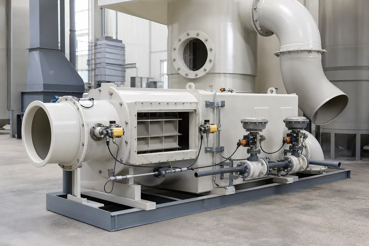
For corrosion-resistant fans and PP ducting, the key points are airflow reliability and static electricity control. PP is corrosion resistant for many acid and alkali exhausts, but VOC service must be reviewed carefully. The fan should have enough pressure margin so that filters, demisters, packed beds, and dampers do not reduce airflow below the safe dilution rate.
Useful checks during design review:
- Minimum exhaust airflow at lowest VFD speed
- Fan curve at dirty filter or wet packing pressure drop
- Damper fail position during power or air failure
- Whether dilution damper fails open
- Whether the process stops if exhaust fan trips
- Whether LEL high alarm stops solvent feed before stopping exhaust
- Whether the treatment unit has safe purge before restart
A common mistake is to stop the fan immediately during a high LEL alarm. In many cases, this traps solvent vapour in the duct and equipment. Usually, the safer action is to stop the VOC source while keeping ventilation and dilution running, unless the site hazard analysis says otherwise.
Practical Next Step
To specify an LEL monitoring and dilution interlock, prepare the following data before contacting an equipment supplier:
- Solvent name or mixture composition
- Maximum and average solvent evaporation rate in kg/h
- Exhaust airflow range in m³/h, including VFD minimum speed
- Duct layout and distance from process to treatment unit
- Treatment method: carbon adsorber, scrubber, condenser, oxidizer, or combination
- Required alarm levels and shutdown philosophy from your site safety team
With these values, an engineer can calculate the expected %LEL, select sensor locations, define dilution airflow, and write a clear interlock sequence for the VOC system.