Why the Carbon Shape Matters
When engineers compare honeycomb vs pellet activated carbon, they often focus only on adsorption capacity. In real VOC systems, the carbon shape also affects fan power, bed size, replacement method, dust control, and operating stability.
Both honeycomb and pellet carbon use activated carbon as the adsorbent. The main difference is the geometry:
- Honeycomb carbon is formed into blocks with many straight channels, similar to a ceramic catalyst block.
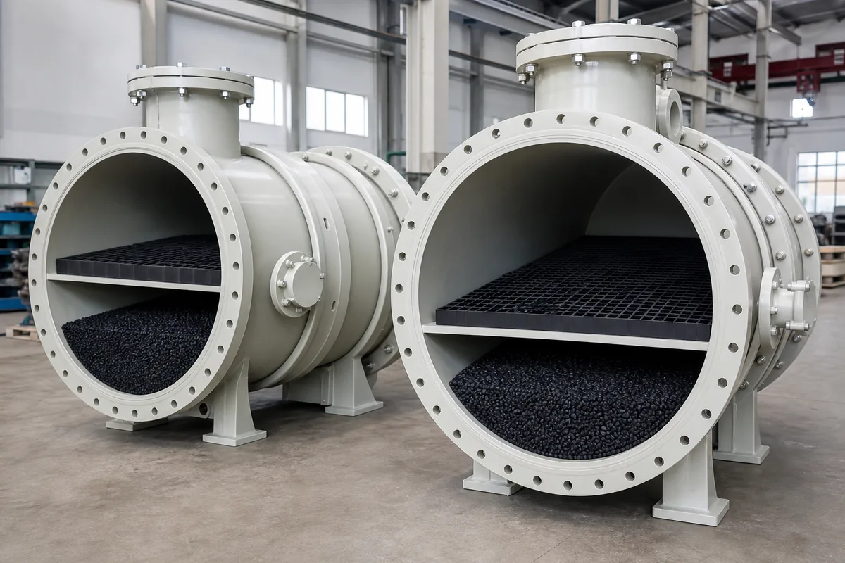
- Pellet carbon is extruded into small cylinders, commonly 3 mm or 4 mm diameter, and filled as a packed bed.
For solvent vapor, odor control, and many industrial VOC applications, both can work. The better choice depends on gas flow, VOC concentration, moisture, required removal efficiency, and maintenance preference.
A useful first rule is:
If pressure drop and fan power are the main limits, honeycomb carbon is usually easier to apply. If adsorption capacity per equipment volume and flexible carbon replacement are the main limits, pellet carbon is often stronger.
But this rule has exceptions, especially when gas velocity, VOC type, and humidity are not controlled.
Pressure Drop and Airflow Design
Pressure drop is the biggest practical difference between honeycomb and pellet carbon.
Honeycomb carbon has straight channels, so the gas path is open and regular. Pellet carbon creates a random packed bed, so the gas must pass through many small voids between pellets. This causes higher resistance.
Typical clean-bed pressure drop ranges:
| Carbon type | Typical face velocity | Typical bed depth | Approx. pressure drop |
|---|---|---|---|
| Honeycomb activated carbon | 0.6–1.2 m/s | 300–600 mm | 300–900 Pa |
| Pellet activated carbon | 0.2–0.5 m/s | 600–1200 mm | 800–2500 Pa |
| Granular activated carbon, irregular | 0.15–0.4 m/s | 600–1200 mm | 1000–3000 Pa |
These are engineering ranges, not guarantees. Pressure drop depends on channel size, pellet diameter, bed depth, dust loading, moisture, and gas velocity.
For pellet beds, pressure drop rises strongly with velocity. A simple rule of thumb is:
`text If gas velocity doubles, pressure drop may increase by about 3–4 times. `
This is why pellet carbon beds are usually designed with lower superficial velocity. For example:
`text Airflow = 10,000 m³/h Velocity target for pellet bed = 0.35 m/s
Required bed area = 10,000 / 3600 / 0.35 = 7.94 m² `
For honeycomb carbon at 0.9 m/s:
`text Required bed area = 10,000 / 3600 / 0.9 = 3.09 m² `
So the honeycomb unit can often be smaller in cross-section, or it can use a lower fan pressure. This is important for retrofits where the existing corrosion-resistant fan has limited static pressure.
However, low pressure drop is not the same as high adsorption performance. Gas must have enough contact time with the carbon surface.
Adsorption Capacity and Contact Time
Activated carbon does not remove VOC by chemical magic. It works by adsorption into pores. Capacity depends on:
- VOC molecular weight and boiling point
- Inlet VOC concentration
- Temperature
- Relative humidity
- Carbon pore structure
- Contact time
- Required outlet concentration
- Whether single solvent or mixed VOC stream
For many organic solvents, practical working capacity may be much lower than laboratory iodine value or CTC value suggests. A conservative design should use working capacity, not total saturated capacity.
Typical working capacity ranges for VOC service:
| VOC condition | Practical working capacity estimate |
|---|---|
| Light, low-boiling VOCs such as methanol or acetone | 3–10% by carbon weight |
| Medium solvents such as toluene, xylene, MEK, ethyl acetate | 8–25% by carbon weight |
| Heavy odor compounds or high-boiling organics | 15–35% by carbon weight |
| High humidity gas stream | Reduce capacity, sometimes by 20–50% |
Pellet carbon usually has higher carbon mass per equipment volume because the packed bed has more adsorbent density. Honeycomb blocks include open channels, so the carbon mass per m³ of bed is lower.
Approximate bulk densities:
| Carbon form | Typical bulk density |
|---|---|
| Honeycomb activated carbon | 350–500 kg/m³ |
| Pellet activated carbon | 450–650 kg/m³ |
| Granular activated carbon | 400–550 kg/m³ |
Because of this, a pellet system may hold more carbon in the same vessel volume. That can mean longer replacement interval if pressure drop is acceptable.
A basic carbon life estimate is:
`text Carbon life (h) = Carbon mass (kg) × working capacity fraction ÷ VOC mass load (kg/h) `
VOC mass load can be estimated as:
`text VOC mass load (kg/h) = Airflow (m³/h) × VOC concentration (mg/m³) ÷ 1,000,000 `
Example:
`text Airflow = 12,000 m³/h VOC concentration = 300 mg/m³ VOC mass load = 12,000 × 300 ÷ 1,000,000 = 3.6 kg/h `
If the adsorber contains 2,000 kg carbon and the estimated working capacity is 15%:
`text Carbon life = 2,000 × 0.15 ÷ 3.6 = 83 hours `
This number is before safety factor. In real design, many engineers apply a safety factor of 0.5–0.7 for mixed VOCs, humidity, uneven flow, and breakthrough limits.
Cost Drivers Beyond Carbon Purchase
Procurement teams often ask which is cheaper. The correct answer is: it depends on the whole system, not only carbon unit cost.
The main cost drivers are different.
| Item | Honeycomb carbon | Pellet carbon |
|---|---|---|
| Fan energy | Usually lower because pressure drop is lower | Usually higher due to packed-bed resistance |
| Equipment footprint | Often smaller cross-section possible | Larger cross-section needed for low velocity |
| Carbon mass installed | Usually lower per m³ bed | Usually higher per m³ bed |
| Replacement labor | Blocks are handled one by one | Pellets need unloading and refilling |
| Dust risk | Usually lower, but blocks can break if mishandled | Higher dust generation during filling/unloading |
| Bed settling | Not typical if blocks are supported correctly | Possible settling and channeling if filling is poor |
| Sensitivity to particulate | Channels may plug if dusty gas is not filtered | Bed surface can blind; dust increases pressure drop |
| Best fit | High airflow, low concentration, limited fan pressure | Higher capacity need, longer adsorption cycle |
Fan power can be estimated:
`text Fan shaft power (kW) = Airflow (m³/s) × Total pressure (Pa) ÷ Fan efficiency ÷ 1000 `
Example for 20,000 m³/h:
`text Airflow = 20,000 ÷ 3600 = 5.56 m³/s Fan efficiency = 0.60 `
If honeycomb bed pressure drop is 700 Pa:
`text Power = 5.56 × 700 ÷ 0.60 ÷ 1000 = 6.5 kW `
If pellet bed pressure drop is 1800 Pa:
`text Power = 5.56 × 1800 ÷ 0.60 ÷ 1000 = 16.7 kW `
The difference is about 10 kW during operation, before adding ducting, demister, filters, and stack losses. For a plant running 8,000 hours/year, this becomes a significant energy difference.
But if pellet carbon gives much longer service life, the maintenance saving may offset the higher fan energy. The correct comparison should include:
- Carbon replacement frequency
- Labor and downtime
- Disposal or regeneration method
- Fan motor size and electricity use
- Space available for the adsorber
- Pre-filter and mist removal requirements
- Expected VOC loading variation
No single carbon shape is always the lowest total cost.
Application Selection Rules
For practical selection, start with the process conditions.
Honeycomb carbon is often suitable when:
- Airflow is large, for example above 10,000–20,000 m³/h
- VOC concentration is low to moderate, often below 500 mg/m³
- Existing fan pressure margin is limited
- The plant wants compact equipment
- Gas is relatively clean after pre-filtration
- Replacement by block modules is preferred
Pellet carbon is often suitable when:
- Higher carbon inventory is needed in the vessel
- VOC concentration is moderate and stable
- Longer adsorption cycle is important
- The plant can accept higher pressure drop
- The system has enough space for a larger bed area
- Proper filling, leveling, and dust control are available
For either type, several design limits are important:
- Temperature
Many VOC adsorption systems are designed below 40°C. Higher temperature reduces adsorption capacity. Some solvents also increase fire risk.
- Humidity
Relative humidity above 70% can reduce capacity, especially for water-soluble VOCs. Install a mist eliminator after a wet scrubber if carbon is downstream.
- Dust and aerosol
Carbon beds are not filters. Use pre-filters or demisters. Oil mist, paint mist, resin droplets, and acid mist can permanently foul carbon.
- Inlet concentration stability
Avoid sudden high-concentration peaks. For solvent vapors, keep well below lower explosive limit and use appropriate safety controls.
- Bed bypass
Poor sealing causes untreated gas to pass around the carbon. This is common in low-quality adsorbers and can make good carbon perform badly.
- Fire prevention
Activated carbon can heat up when adsorbing high VOC loads, ketones, or reactive compounds. Temperature monitoring and correct operating procedures are important.
In combined systems, carbon is often placed after a PP wet scrubber when the gas contains both acid/alkali gases and VOCs. The scrubber removes soluble corrosive gases and cools the stream, while the carbon removes remaining organic vapor. In this arrangement, moisture control is critical. A good demister and drain design protect the carbon bed.
Practical Next Step
Before choosing honeycomb vs pellet activated carbon, prepare a simple data sheet with airflow, VOC names, inlet concentration range, temperature, humidity, dust or mist content, and required outlet target. Also record available fan static pressure and installation space.
With these values, an equipment supplier can estimate bed size, pressure drop, carbon mass, and replacement interval for both options. Then compare the total system: not only carbon capacity, but also fan power, maintenance method, and risk of plugging or bypass.