Why Breakthrough Is a Maintenance Problem, Not Only a Compliance Problem
Activated carbon adsorbers are simple machines, but carbon breakthrough can happen quickly when operating conditions change. In many plants, the first clear sign is an odor complaint, a stack test failure, or an alarm from a downstream VOC monitor. By that time, the carbon bed may already be saturated, and the plant may have released pollutants above its permit limit.
Carbon breakthrough detection means identifying when contaminants begin to pass through the carbon bed before the outlet concentration becomes unacceptable. For plant engineers and maintenance teams, this is mainly a control problem: you need enough information to know when to change carbon, when to switch beds, and when to investigate process changes.
Breakthrough is not a single fixed point. It depends on:
- Inlet VOC type and concentration
- Gas flow rate and bed contact time
- Temperature and humidity
- Carbon type, particle size, and loading capacity
- Bed depth and gas distribution
- Presence of aerosols, dust, acid gas, or condensable vapors
A carbon adsorber that worked for six months in stable service may break through in six weeks if solvent loading doubles or humidity rises sharply.
A useful rule is: do not manage activated carbon only by calendar time. Calendar replacement is easy, but it is often either too early, wasting carbon, or too late, risking emission problems.
Understanding the Breakthrough Curve
In a fixed carbon bed, VOCs are first captured near the inlet side. Over time, the active adsorption zone moves through the bed toward the outlet. This moving zone is often called the mass transfer zone.
At the beginning, outlet concentration is near zero. Later, a small amount of contaminant appears at the outlet. Finally, outlet concentration rises rapidly and approaches inlet concentration. This is the breakthrough curve.
A simplified way to describe it:
`text Breakthrough ratio = Cout / Cin `
Where:
Cin= inlet contaminant concentrationCout= outlet contaminant concentration
Typical engineering reference points are:
Cout/Cin = 0.01or 1%: early breakthroughCout/Cin = 0.05or 5%: common warning levelCout/Cin = 0.10or 10%: often treated as a serious action levelCout/Cin > 0.50: bed is largely exhausted for that contaminant
The exact action level depends on the emission limit, safety factor, and process risk. For example, if the inlet concentration is 800 ppmv and the permit outlet limit is 50 ppmv, then the maximum allowable ratio is:
`text 50 / 800 = 0.0625 = 6.25% `
In this case, waiting until 10% breakthrough would be too late. A warning alarm at 2–3% and a changeover alarm at 5% may be more practical.
Empty bed contact time, or EBCT, is also important:
`text EBCT (s) = carbon bed volume (m³) / gas flow rate (m³/s) `
For many VOC polishing applications, EBCT is often in the range of 0.5 to 2.0 seconds. For low-concentration odor control, it may be longer. For high-solvent loading, carbon adsorption alone may not be suitable unless there is regeneration, condensation, or another upstream treatment step.
Field Methods for Carbon Breakthrough Detection
There is no single best method for all plants. The correct method depends on the VOC mixture, concentration, regulatory risk, and maintenance capability.
| Method | What it measures | Typical use | Advantages | Limitations |
|---|---|---|---|---|
| PID handheld meter | Total ionizable VOCs | Periodic checks at sample ports | Fast, portable, useful for trends | Response factor varies by compound; affected by humidity and lamp energy |
| FID analyzer | Total hydrocarbons | Continuous or semi-continuous monitoring | Stable for many hydrocarbons; good for compliance trend | Needs fuel gas; does not identify compounds |
| GC or GC-MS sampling | Individual compounds | Laboratory confirmation | Accurate speciation; useful for mixed solvents | Slow; not ideal for real-time alarms |
| Colorimetric tubes | Specific gases or vapors | Low-frequency maintenance checks | Low cost and simple | Limited accuracy; manual reading; compound-specific |
| LEL sensor | Flammable gas risk | Safety monitoring | Important for explosion prevention | Not sensitive enough for low ppm breakthrough |
| Odor observation | Human detection | Early nuisance warning | Very sensitive for some sulfur/amine compounds | Not quantitative; unsafe to rely on alone |
For many factories, a practical setup is:
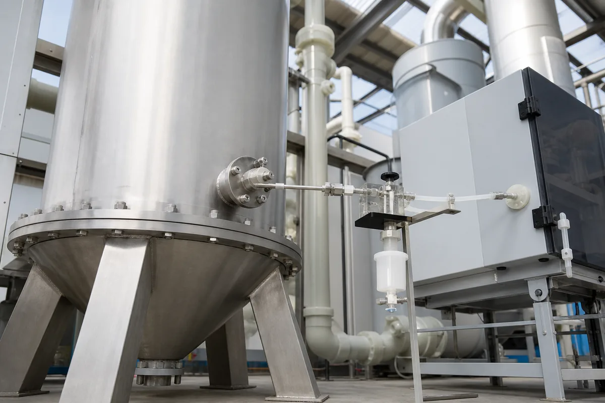
- Install inlet and outlet sample ports on each carbon vessel.
- Use a PID or FID for routine trend monitoring.
- Send laboratory samples when the VOC mixture changes or when readings are unclear.
- Set alarm values based on the actual outlet limit, not a generic percentage.
Sample port design is often overlooked. Ports should be located in straight duct sections where the gas is well mixed. Avoid placing the outlet sample point immediately after an elbow, fan discharge, or damper. If the duct is large, a single-point sample may not represent the full flow. In critical systems, use multi-point sampling or a traverse during commissioning.
Warning Signs Before the Outlet Alarm
Breakthrough is not always caused by the carbon reaching its normal working capacity. Often it is caused by operating conditions that reduce adsorption performance.
Common warning signs include:
- Rising outlet VOC trend, even if still below the limit
- Shorter carbon life compared with previous cycles
- Higher bed temperature, especially after process changes
- Pressure drop increase, suggesting dust, mist, or carbon fouling
- Pressure drop decrease, suggesting channeling, bed settling, or bypass
- Condensation in ducting, which can block pores and reduce capacity
- Strong odor after the adsorber, especially during startup or batch discharge
- Uneven carbon temperature, indicating poor gas distribution or localized adsorption heat
Temperature is important because adsorption capacity generally decreases as temperature increases. As a rule of thumb, many VOC adsorption systems perform best below 40°C. Above 50–60°C, capacity may fall significantly, depending on the compound and carbon type. High humidity also competes with VOC adsorption, especially for water-soluble or polar compounds. Relative humidity above 70% can reduce effective capacity in some applications.
Dust and oil mist are also serious. Activated carbon is a porous material. If particles, resin mist, or plasticizer aerosols coat the carbon, the bed may fail early even though the carbon is not chemically saturated. In such cases, replacing carbon without improving pre-filtration only repeats the problem.
A normal pressure drop depends on bed depth, carbon particle size, and gas velocity. For many granular carbon beds, superficial velocity is commonly designed around 0.2 to 0.5 m/s. Pressure drop may be in the range of 800 to 2000 Pa, but this must be checked against the actual vessel size and carbon specification. Sudden changes are more important than the absolute value.
Setting a Practical Monitoring Plan
A monitoring plan should be simple enough for operators to follow every week. It should also provide enough data to avoid surprise failures.
For a single-pass carbon adsorber, the minimum plan should include:
- Inlet VOC concentration
- Outlet VOC concentration
- Gas flow rate
- Gas temperature
- Relative humidity, if high or variable
- Pressure drop across the bed
- Operating hours since carbon change
- Process condition, such as coating line speed or solvent use rate
A useful carbon loading estimate is:
`text VOC mass load (kg/h) = flow (m³/h) × concentration (mg/m³) / 1,000,000 `
Then:
`text Estimated captured mass (kg) = VOC mass load × operating hours × removal efficiency `
Example:
- Gas flow: 10,000 m³/h
- Inlet VOC: 300 mg/m³
- Outlet VOC before breakthrough: 15 mg/m³
- Removal efficiency: 95%
- Operating time: 1,000 h
`text VOC mass load = 10,000 × 300 / 1,000,000 = 3 kg/h Captured mass = 3 × 1,000 × 0.95 = 2,850 kg `
If the carbon charge is 10,000 kg, the apparent working loading is:
`text 2,850 / 10,000 = 28.5% by weight `
This may be reasonable for some solvents, but high for others. Actual working capacity may range from 5% to 35% by weight, depending strongly on the VOC. Light, low-boiling compounds often have lower capacity. Heavy solvents may have higher capacity but may also create fire or desorption problems if heat builds up.
For high-risk applications, consider a lead-lag arrangement. Two carbon beds are installed in series. The first bed does most of the work. The second bed protects the stack. Breakthrough is monitored between the two beds and at the final outlet.
This arrangement gives maintenance time:
- When VOC appears after the lead bed, replace or regenerate the lead bed.
- Move the lag bed to lead position if the design allows.
- Install fresh carbon in the lag position.
- Keep final outlet emissions protected during the change cycle.
Lead-lag systems are especially useful when the plant cannot stop production immediately.
Next Step: Check Your Detection Points Before Changing Carbon
Before ordering another carbon replacement, review your current detection method. Confirm that you have sample ports at the inlet, outlet, and, for two-bed systems, between beds. Record VOC trend, temperature, humidity, pressure drop, and operating hours for at least one full carbon cycle.
If you are designing a new adsorber or troubleshooting early breakthrough, prepare these data before contacting an equipment supplier:
- Exhaust flow rate, normal and maximum
- VOC names and concentrations
- Temperature and humidity
- Dust, mist, or acid gas content
- Required outlet limit
- Operating schedule
- Existing duct size and fan pressure margin
With these numbers, an engineer can size the carbon bed, select suitable pre-treatment, and define a carbon breakthrough detection plan that gives warning before the regulator does.