Basic Reaction and Process Flow
The catalytic oxidizer working principle is simple: VOCs in exhaust gas are oxidized to carbon dioxide and water on the surface of a catalyst at a lower temperature than direct thermal oxidation. The catalyst does not “burn” the VOC by itself. It provides active sites that reduce the activation energy of the oxidation reaction.
For most hydrocarbon VOCs, the simplified reaction is:
`text CxHy + (x + y/4) O2 → x CO2 + (y/2) H2O + heat `
For oxygenated VOCs, such as alcohols, ketones, esters and aldehydes, the formula is similar but the oxygen already present in the molecule must be considered. For chlorinated, sulfur-containing or nitrogen-containing compounds, catalytic oxidation needs special review because acid gases or catalyst poisons may be formed.
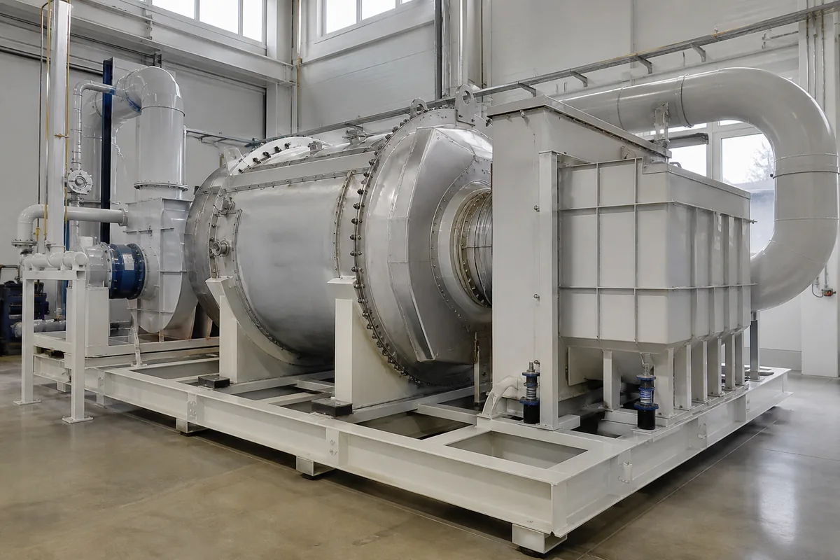
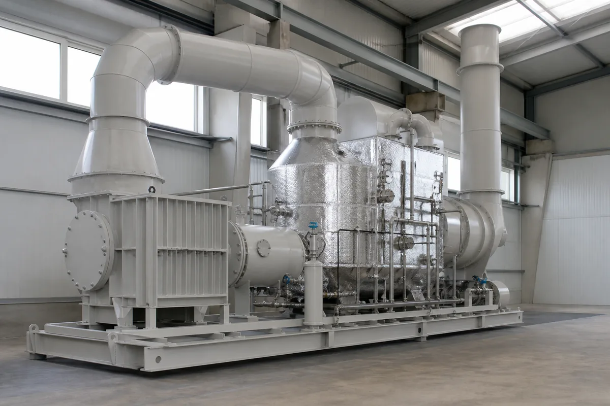
A typical catalytic oxidizer includes:
- Inlet duct and pre-filter
Removes dust, mist and sticky particles before the catalyst.
- Heat exchanger
Uses hot treated gas to preheat incoming gas. This reduces auxiliary fuel or electric heating demand.
- Burner or electric heater
Raises the gas to catalyst inlet temperature during start-up or low VOC loading.
- Catalyst bed
Usually ceramic or metallic honeycomb coated with precious metal or metal oxide catalyst.
- Temperature measurement and controls
Normally includes inlet temperature, catalyst bed temperature and outlet temperature.
- Exhaust fan and stack
Maintains the designed airflow and pressure balance.
The main design target is to keep the catalyst at a temperature where VOC conversion is high, while avoiding overheating, fouling or poisoning.
Operating Temperature: What Range Is Practical?
Catalytic oxidizers normally operate at lower temperature than thermal oxidizers. A common operating range is:
- Catalyst inlet temperature: 250–400°C
- Catalyst bed temperature: 300–550°C, depending on VOC concentration and heat release
- Maximum continuous catalyst temperature: often around 500–650°C, depending on catalyst type and supplier limits
These numbers are not universal. They depend on the VOC type, concentration, catalyst formulation, oxygen content, moisture, residence time and required destruction efficiency.
Light and easily oxidized compounds such as alcohols and many solvents can often be treated at lower temperatures. Aromatics, some ketones and mixed VOC streams may require higher temperature. Chlorinated or silicon-containing compounds are more difficult and may not be suitable for standard precious-metal catalysts.
A practical rule is:
`text Required catalyst inlet temperature = light-off temperature + safety margin `
The light-off temperature is the temperature where a specific VOC begins to oxidize significantly on a catalyst. In real equipment, engineers usually add a safety margin of 30–80°C because gas composition, airflow and inlet concentration will fluctuate.
For example, if a mixed solvent stream has stable conversion above 280°C in laboratory testing, a practical catalyst inlet setpoint may be 320–350°C.
Temperature control is important because both low and high temperatures create problems:
| Condition | Typical Cause | Result | Practical Action |
|---|---|---|---|
| Too low catalyst inlet temperature | Low heater output, cold start, high airflow | VOC slip, odor at stack | Increase preheat, reduce airflow during start-up, check heater |
| Normal inlet but high bed temperature | High VOC concentration, poor dilution | Catalyst overheating risk | Add LEL control, dilution air, concentration monitoring |
| Gradual higher temperature needed | Catalyst aging or fouling | Lower conversion at same setpoint | Inspect pre-filter, test pressure drop, consider catalyst cleaning/replacement |
| Sudden temperature rise | Solvent slug or process upset | Safety risk, possible catalyst damage | Interlock process source, open bypass if designed, alarm on high temperature |
Catalyst Selection and Bed Design
The catalyst is the heart of the system. Common forms include ceramic honeycomb, metallic honeycomb and pellet catalyst. In industrial VOC oxidizers, honeycomb catalyst is widely used because it provides high surface area and relatively low pressure drop.
Two common catalyst families are:
- Precious metal catalyst
Usually based on platinum, palladium or a combination. Good for many hydrocarbons, alcohols, ketones and esters. Sensitive to poisons such as sulfur, phosphorus, heavy metals, silicones and halogens.
- Base metal oxide catalyst
Often used where precious metal catalyst may not be ideal. It may tolerate some compounds better, but often requires higher operating temperature. Suitability depends strongly on gas composition.
Important design parameters include space velocity, gas velocity, pressure drop and inlet distribution.
A common calculation is gas hourly space velocity:
`text GHSV = Gas flow rate at operating condition (m³/h) / Catalyst volume (m³) `
Typical GHSV values for VOC catalytic oxidation may be 10,000–40,000 h⁻¹. Lower GHSV means longer contact time and usually higher conversion, but larger catalyst volume. Higher GHSV means smaller equipment but higher risk of incomplete oxidation.
Face velocity through honeycomb catalyst is often in the range of 1–3 m/s, depending on cell density, pressure drop and mechanical strength. Pressure drop through a clean catalyst bed may be roughly 300–1500 Pa, depending on bed depth, honeycomb cell size and velocity. The full system pressure drop, including heat exchanger, ducting and filters, is usually much higher and must be matched with the fan.
Good catalyst performance also requires even gas distribution. A poor inlet plenum can cause part of the catalyst to carry most of the flow, while other areas are underused. This creates low conversion and local hot spots. For compact systems, we normally pay close attention to:
- Straight duct length before the reactor, where possible
- Flow distribution plates or perforated plates
- Smooth transition angles, often below 30° when space allows
- Easy access for catalyst inspection and replacement
- Differential pressure ports before and after catalyst
Autothermal Point and Heat Balance
The autothermal point is the VOC concentration where the heat released by oxidation is enough to maintain the required catalyst inlet temperature without auxiliary heating, after considering heat exchanger recovery and heat losses.
In simple words: above this point, the oxidizer can run hot by using the VOC as fuel. Below this point, it needs extra heat.
A simplified heat balance is:
`text Heat from VOC oxidation + Heat recovered by exchanger = Heat needed to raise inlet gas temperature + Heat losses `
For quick estimation, the heat needed to raise air temperature is:
`text Q = Flow × Density × Cp × ΔT `
Where:
Q= heat duty, kWFlow= gas flow, m³/sDensity= about 1.2 kg/m³ at ambient air, lower at high temperatureCp= about 1.0 kJ/kg·K for airΔT= temperature rise, K or °C
The heat released by VOC depends on its lower heating value. A rough rule for many solvent VOCs is:
`text 1 g/Nm³ VOC ≈ 2–4 kJ/Nm³ heat release `
This is only a rough estimate. Toluene, ethanol, ethyl acetate, acetone and mixed paint solvents have different heating values. Water vapor and inert gas also affect the heat balance.
Example:
- Airflow: 10,000 Nm³/h
- Inlet gas temperature: 30°C
- Catalyst inlet target: 320°C
- Temperature rise needed without recovery: 290°C
- Heat needed approximately:
`text 10,000 Nm³/h × 1.2 kg/Nm³ × 1.0 kJ/kg·K × 290 K = 3,480,000 kJ/h ≈ 967 kW `
If the heat exchanger has 70% thermal recovery, the auxiliary heating demand can be reduced significantly. The remaining required heat may be around 290 kW, plus losses. If VOC heat release supplies this amount, the system approaches autothermal operation.
In real design, the autothermal point must be calculated with actual VOC composition, exhaust moisture, heat exchanger efficiency, reactor insulation, airflow turndown and safety dilution. It is not a fixed concentration. For many catalytic oxidizer systems with heat recovery, autothermal operation may occur at a few hundred to a few thousand mg/Nm³ VOC, depending on the solvent.
One important warning: a high VOC concentration can save energy, but it also increases safety risk. The inlet concentration should normally be kept well below the lower explosive limit. Many plants use a control limit of 25% LEL for continuous operation, but the correct limit depends on local rules, risk assessment and instrument design.
Practical Design and Operation Checks
A catalytic oxidizer is not only a reactor. It is part of a process exhaust system. Before selecting equipment, collect stable and peak values for airflow, temperature and VOC concentration. Short peaks are important because they can overheat the catalyst even when average concentration is safe.
Useful design data includes:
- Normal, minimum and maximum airflow in Nm³/h
- Gas temperature and humidity
- VOC list with concentration range in mg/Nm³ or ppm
- Dust, oil mist, resin, tar or aerosol content
- Halogen, sulfur, phosphorus or silicone compounds
- Oxygen content
- Required removal efficiency
- Operation schedule, such as 8 h/day or 24 h/day
- Available fuel, electricity and compressed air
- Duct pressure and fan location
Maintenance staff should also monitor several simple indicators:
`text Catalyst performance trend = outlet VOC trend at same inlet load and temperature `
If outlet VOC slowly increases, possible causes include catalyst aging, poison exposure, plugging or poor temperature control.
`text Fouling trend = pressure drop increase across filter and catalyst `
A rising pressure drop means dust, mist or polymerized material may be blocking the system. This can reduce airflow and create uneven catalyst temperature.
Good upstream treatment is often cheaper than early catalyst replacement. For painting, coating, printing, rubber, chemical mixing or resin processes, a pre-filter, demister or condenser may be needed before catalytic oxidation. If sticky or high-boiling VOCs are present, the duct and reactor should avoid cold spots where condensation can occur.
Practical Next Step
To evaluate whether catalytic oxidation is suitable, prepare one operating case and one worst-case peak case. Include airflow, VOC composition, concentration, gas temperature, moisture and any catalyst poison risk. With these data, an equipment supplier can estimate catalyst volume, operating temperature, heat recovery, auxiliary heat demand and approximate autothermal point before detailed design.