Why Layout Often Decides the Equipment Shape
When engineers compare a carbon adsorption box vs tower, they often start with carbon type, VOC removal efficiency, or airflow. These are important, but site layout can decide the practical choice earlier.
Both designs use activated carbon to adsorb VOCs or odors from exhaust air. Both can be built in PP, FRP, carbon steel, or stainless steel depending on gas composition and temperature. Both need correct empty bed contact time, low enough face velocity, safe access for carbon replacement, and pressure drop control.
The difference is mainly the gas flow path and equipment geometry:
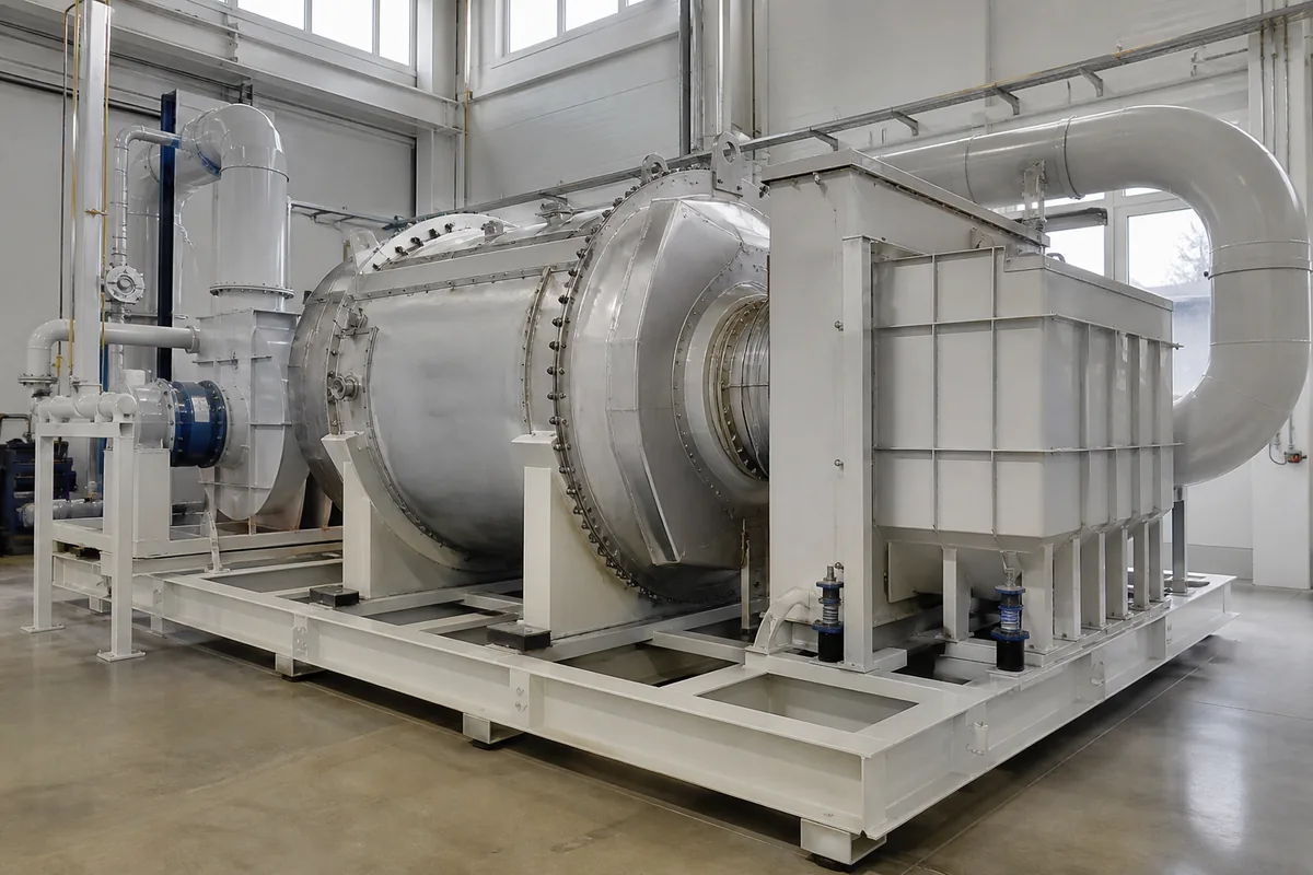
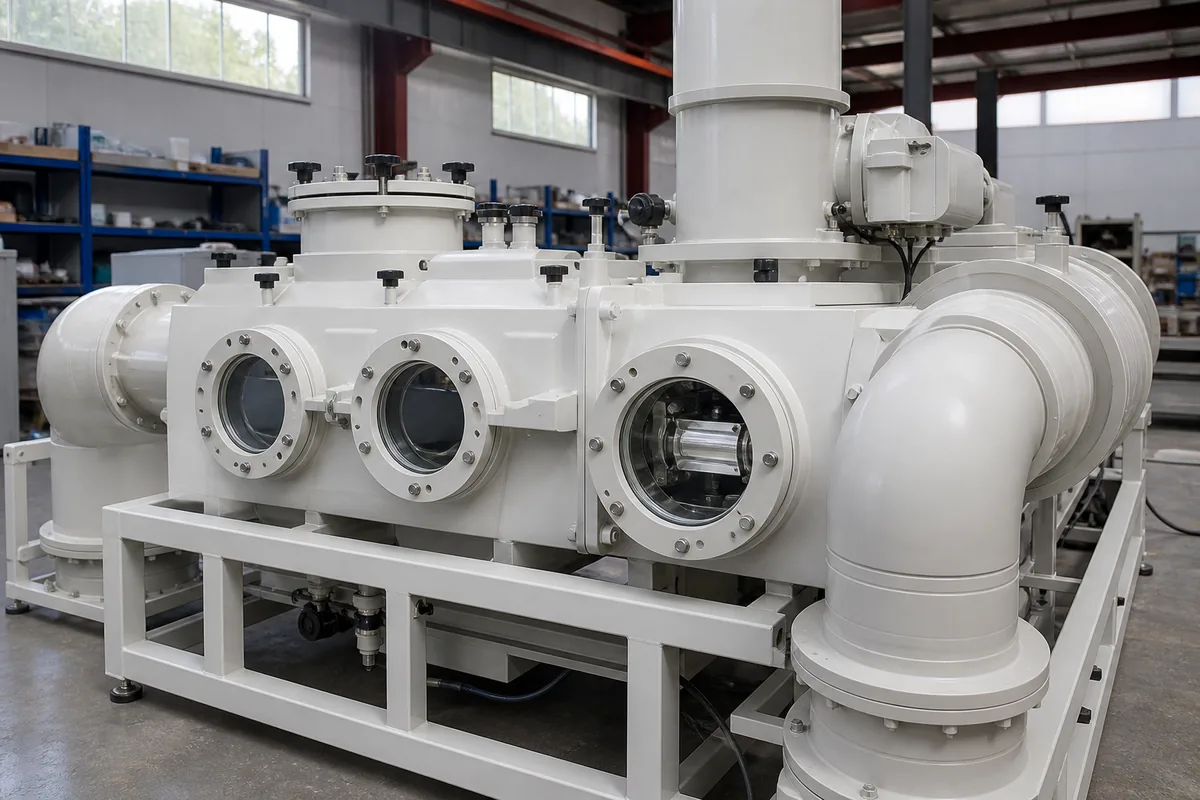
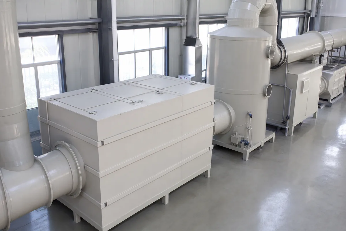
- A carbon box is usually a horizontal rectangular vessel. Air passes through one or more flat carbon beds or cartridges.
- A carbon tower is usually a vertical cylindrical or rectangular vessel. Air passes upward or downward through a deeper carbon bed.
For many small and medium VOC systems, both can technically work. The better choice depends on floor space, headroom, duct routing, maintenance method, carbon quantity, and future expansion.
Footprint, Height, and Access Space
The first layout question is simple: do you have more floor area or more vertical height?
A carbon box normally needs more floor area because the bed area is spread horizontally. A carbon tower normally uses less floor area but needs more height for the vessel, top duct, inspection manhole, and carbon loading space.
Typical practical ranges are:
| Item | Carbon adsorption box | Carbon adsorption tower |
|---|---|---|
| Common airflow range per unit | 1,000–30,000 m³/h | 3,000–60,000+ m³/h |
| Main layout shape | Long and low | Tall and compact |
| Typical face velocity through carbon bed | 0.2–0.6 m/s | 0.15–0.5 m/s |
| Typical carbon bed depth | 300–800 mm | 600–1,500 mm |
| Floor space requirement | Higher | Lower |
| Height requirement | Lower | Higher |
| Carbon replacement | Side/front access, trays or drawers | Top loading, bottom/side discharge, manhole access |
| Best for | Low headroom rooms, skid systems, easy side maintenance | Limited floor area, large carbon volume, outdoor installation |
The table gives rules of thumb only. The final size depends on VOC concentration, target outlet concentration, carbon working capacity, gas humidity, temperature, dust loading, and replacement interval.
A useful sizing check is:
`text Bed area A = Airflow Q / Face velocity V `
Where:
A= required bed area, m²Q= airflow, m³/sV= superficial velocity through carbon bed, m/s
Example: for 10,000 m³/h:
`text Q = 10,000 / 3,600 = 2.78 m³/s If V = 0.35 m/s A = 2.78 / 0.35 = 7.9 m² `
That bed area may become a wide horizontal box, or a vertical tower with a suitable diameter or rectangular cross-section.
For indoor installations, also check:
- Minimum clearance for removing carbon cartridges or trays
- Space for forklift, trolley, vacuum loader, or carbon bags
- Door size and route from unloading area to equipment room
- Height under beams, pipe racks, cable trays, and sprinkler piping
- Safe access platform if the tower manhole is above normal working height
A compact vessel is not always compact after adding service clearance.
Duct Routing and Fan Position
Duct layout can make one option much easier than the other.
A carbon box is convenient when the inlet duct comes horizontally from production equipment and the outlet duct continues horizontally to the fan or stack. It can be installed inline, similar to a filter box. This is useful in workshops with low roof height or where exhaust duct already runs along a wall.
A tower is often better when ducting needs to turn upward to a stack, or when the fan and stack are installed after the tower outdoors. The vertical arrangement can reduce ground congestion. However, the inlet and outlet nozzles must be arranged carefully to avoid uneven flow distribution.
For both types, avoid connecting a small duct directly to a large carbon bed without a proper transition. Poor distribution causes part of the carbon bed to saturate early while other areas are unused.
Good layout practice includes:
- Use a duct transition angle of about 15–30° where space allows.
- Provide a perforated plate, diffuser, or inlet plenum for large units.
- Keep at least 1 duct diameter of straight duct before the inlet if possible.
- Avoid sharp elbows immediately before the carbon bed.
- Install sampling ports before and after the adsorber.
- Install differential pressure gauges across the bed.
Pressure drop is also part of layout planning. A clean activated carbon bed may have a pressure drop of approximately 500–1,500 Pa, depending on bed depth, pellet size, velocity, and internal structure. With prefilters, mist eliminators, ducting, and stack losses, the fan static pressure may need to be much higher. The fan should be selected for the full system, not only the adsorber.
If the gas contains acid mist, alkaline mist, oil, resin, or dust, install pretreatment before carbon. Activated carbon is not a dust filter. Blocked carbon increases pressure drop and can create unsafe heat accumulation in some VOC applications.
Maintenance Method and Carbon Handling
Maintenance layout is one of the biggest differences in a carbon adsorption box vs tower comparison.
A carbon box usually allows side or front access. Operators can pull out trays, drawers, or modules. This is convenient when the carbon volume is small to medium and labor access is good. For example, a box containing 200–1,000 kg of activated carbon can often be serviced using bags, trays, and a small trolley, depending on local work rules.
A tower often contains a larger carbon volume. It may be loaded from the top and discharged from the bottom or side. This can be efficient for large systems, but the site must provide access for:
- Lifting carbon bags to the top platform
- Vacuum loading or pneumatic conveying, if used
- Safe discharge into drums, bulk bags, or containers
- Dust control during carbon removal
- Confined space procedures if workers enter the vessel
- Isolation from the fan and process before maintenance
Carbon replacement interval depends strongly on inlet concentration and carbon working capacity. A rough mass balance is:
`text VOC mass per day = Airflow × Concentration × Operating hours `
Using SI units:
`text kg/day = (m³/h × mg/m³ × h/day) / 1,000,000 `
Example:
`text Airflow = 8,000 m³/h VOC concentration = 100 mg/m³ Operating time = 10 h/day
VOC load = 8,000 × 100 × 10 / 1,000,000 = 8 kg/day `
If the effective working capacity of the carbon for that VOC mixture is 10% by mass, then 1,000 kg of carbon may adsorb about 100 kg before breakthrough under that condition. The actual value may be lower with high humidity, high temperature, mixed solvents, or poor pretreatment.
For layout, this means: do not only ask “Can the unit fit?” Ask “Can we safely replace the carbon every planned cycle?”
Indoor, Outdoor, and Structural Considerations
Carbon boxes are often easier to install indoors because of lower height and easier side access. They can be placed beside production lines, on a mezzanine, or inside an equipment room. However, the longer footprint may block walkways or reduce forklift movement.
Carbon towers are common outdoors or in plant yards because height is less restricted. They can be installed near a scrubber, fan, and stack. But outdoor installation requires attention to wind load, foundation, corrosion, rain protection, and access platforms.
For PP construction, temperature and mechanical support are important. PP has good corrosion resistance for many acidic and alkaline gases, but its allowable strength decreases as temperature rises. As a general rule, PP equipment is commonly used below 70–80°C, depending on design, thickness, reinforcement, and service condition. For higher temperature VOC streams, cooling or another material may be required.
Other layout checks:
- Foundation load: Include vessel weight, carbon weight, liquid from washing or condensation, and maintenance loads.
- Vibration: Keep the fan on a suitable base or flexible connection. Do not transfer fan vibration into a PP vessel.
- Drainage: Provide drains for condensate or washing water if needed.
- Fire safety: Some VOCs can heat carbon during adsorption. Avoid high inlet concentration, oxidizing gases, sparks, and hot particles. Consider temperature monitoring for higher-risk applications.
- Humidity: Relative humidity above about 70% can reduce adsorption capacity for many VOCs. If mist is present, use a demister or prefilter.
A tower with a deep bed may hold more carbon in a smaller footprint, but it also concentrates more weight in one area. A box spreads the load over a larger base, which may help on some floors.
Choosing Between Box and Tower
There is no universal winner. The better choice is the one that fits the airflow, carbon mass, maintenance plan, and available space with the least duct complication.
A carbon box is usually preferred when:
- Headroom is limited.
- The system is small or medium airflow.
- Horizontal inline duct routing is convenient.
- Operators need simple side access.
- Carbon modules or trays are preferred.
- The unit must be placed inside a workshop or on a skid.
A carbon tower is usually preferred when:
- Floor area is limited but height is available.
- Larger carbon volume is required.
- Outdoor installation is acceptable.
- Top loading and bottom discharge are practical.
- The exhaust route naturally goes upward to a stack.
- Future airflow increase may need a larger bed volume.
For borderline cases, compare the total installed layout, not just vessel dimensions. Include duct transitions, fan position, maintenance clearance, platform, carbon handling route, and sample port access. A smaller vessel drawing can become a larger installation after these items are added.
Practical Next Step
Before asking a supplier to select a carbon box or tower, prepare a simple site layout sketch with airflow direction, available length, width, height, duct sizes, fan location, and maintenance access route. Also provide airflow, VOC type, inlet concentration, temperature, humidity, operating hours, and any dust or mist condition. With this information, the equipment shape can be selected based on real installation constraints, not only catalogue dimensions.