Where This Process Fits
Carbon adsorption catalytic desorption is used when a plant needs to treat medium- to low-concentration VOC exhaust and recover or destroy the adsorbed solvent in a controlled regeneration cycle. It is common for coating, printing, electronics, chemical storage, composite materials, rubber, and packaging processes.
The basic idea is simple:
- VOC-laden air passes through activated carbon beds.
- VOC molecules are adsorbed onto the carbon surface.
- When the carbon approaches saturation, the bed is taken offline.
- Hot air or inert gas desorbs the VOC from the carbon.
- The concentrated desorption gas goes to a catalytic oxidation unit.
- The cleaned hot gas can be partly reused for heating the next desorption step.
This system is different from a once-through activated carbon adsorber. The carbon is regenerated many times, so the carbon consumption is much lower. It is also different from direct catalytic oxidation of the whole exhaust stream. Because adsorption concentrates the VOC, the catalytic reactor treats a smaller airflow with higher VOC concentration.
A typical application range is:
- Exhaust airflow: 5,000 to 100,000 m³/h per system
- Inlet VOC concentration: often 100 to 1,500 mg/m³, depending on solvent type
- Desorption airflow: usually 5% to 15% of adsorption airflow
- Catalytic oxidation temperature: commonly 250 to 350°C
- Activated carbon bed face velocity: usually 0.2 to 0.6 m/s
- Adsorption cycle time: often 4 to 12 hours, but must be calculated from VOC loading
These numbers are starting points, not universal design values. Solvent composition, humidity, dust, temperature, and required outlet concentration can change the design strongly.
Main Equipment in the Cycle
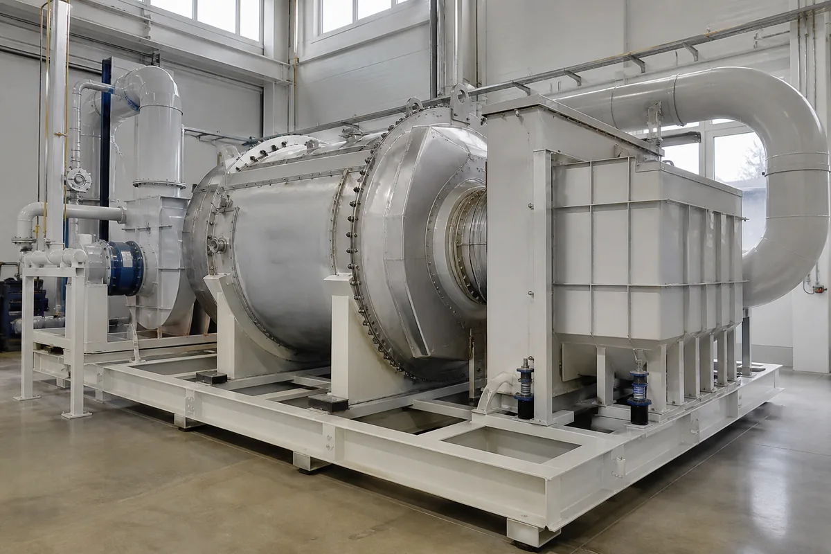
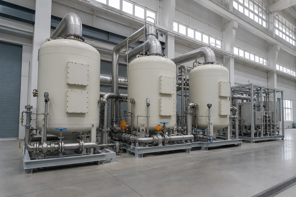
A complete carbon adsorption catalytic desorption system normally includes several main parts. The exact arrangement depends on airflow, VOC type, and whether continuous operation is required.
| Component | Main Function | Key Design Points |
|---|---|---|
| Pre-filter | Removes dust, mist, paint particles, resin aerosols | Protects carbon from blockage and catalyst from poisoning |
| Activated carbon beds | Adsorb VOC from exhaust air | Usually 2 to 4 beds for continuous operation |
| Desorption fan | Circulates hot regeneration air | Smaller flow than main exhaust fan |
| Heater | Raises desorption gas temperature | Electric, steam, thermal oil, or gas heating may be used |
| Catalytic reactor | Oxidizes concentrated VOC to CO₂ and H₂O | Requires suitable temperature and catalyst selection |
| Heat exchanger | Recovers heat from oxidized gas | Reduces heater load |
| Valves and dampers | Switch beds between adsorption, desorption, cooling, standby | Must seal well to avoid VOC leakage |
| Control system | Manages cycle timing, temperature, alarms | Important for safe regeneration |
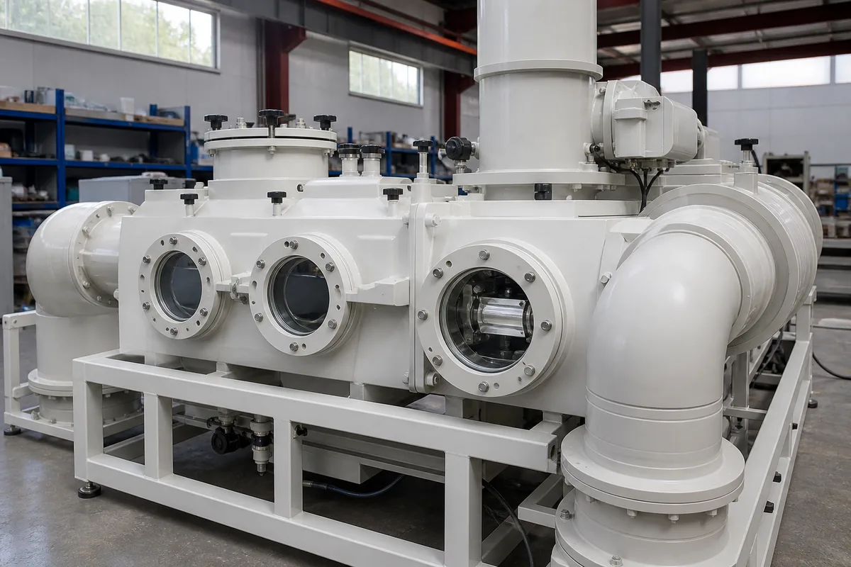
For plastic and corrosion-resistant equipment, PP is suitable for many acidic or alkaline wet gas sections, ducting, and scrubber components. However, high-temperature desorption and catalytic oxidation sections need metal materials because operating temperatures are far above PP limits. PP softening and long-term strength reduction must be considered carefully; for many PP ducts, continuous gas temperature is normally kept below 70 to 90°C, depending on grade, thickness, support spacing, and chemical exposure.
Step-by-Step Operating Cycle
A practical system uses at least two carbon beds. One bed adsorbs while another bed regenerates or cools. Large systems may use three or more beds to make the airflow and outlet VOC concentration more stable.
1. Adsorption
Process exhaust enters the carbon bed after pre-filtration. VOC molecules diffuse into the pores of the activated carbon and are held by physical adsorption.
Important operating checks during adsorption:
- Gas temperature should normally be kept below 40°C for better adsorption capacity.
- Relative humidity should preferably be below 70%. High humidity competes for adsorption sites and reduces capacity for many solvents.
- Dust and oil mist should be removed. A pressure drop increase of 30% to 50% from clean condition is a warning sign.
- Bed face velocity should be controlled. Too high velocity causes short contact time and early breakthrough.
For a rough estimate of adsorption loading:
`text VOC mass per hour = airflow × concentration `
If airflow is in m³/h and concentration is in mg/m³:
`text VOC kg/h = airflow (m³/h) × concentration (mg/m³) ÷ 1,000,000 `
Example:
`text 20,000 m³/h × 500 mg/m³ ÷ 1,000,000 = 10 kg/h VOC `
The usable working capacity of activated carbon is not the same as its laboratory adsorption capacity. For many mixed solvent exhausts, a conservative working capacity may be 5% to 15% by carbon weight before desorption. Strongly adsorbed solvents may be higher; very volatile solvents may be lower.
2. Bed Switching
Before breakthrough occurs, the saturated bed is isolated from the main exhaust. Valves change position so another fresh or regenerated bed takes over adsorption.
Breakthrough should not be judged only by time. It is better to use one or more of the following:
- Outlet VOC monitoring
- Calculated VOC mass loading
- Historical operating data
- Temperature rise across the bed
- Safety margin based on worst-case concentration
A simple cycle time estimate is:
`text Adsorption time = carbon mass × working capacity ÷ VOC mass flow `
Example:
- Carbon mass in one bed: 1,500 kg
- Working capacity: 8%
- VOC loading: 10 kg/h
`text 1,500 × 0.08 ÷ 10 = 12 hours `
In real operation, use a safety factor. If production VOC concentration changes, the time must be adjusted.
3. Heating and Desorption
The isolated bed is heated by a small flow of hot air or inert gas. VOC molecules leave the carbon surface and enter the desorption gas stream.
Typical desorption conditions:
- Desorption gas temperature into carbon bed: 90 to 130°C for many solvent systems
- Desorption time: 1 to 3 hours
- Desorption airflow: 5% to 15% of adsorption airflow
- Bed outlet VOC concentration: can be several times higher than inlet process exhaust
The correct temperature depends on the adsorbed VOC. Low-boiling solvents desorb more easily. Heavy solvents, plasticizers, or high-boiling organics may need longer time and may not regenerate well. If the temperature is too high, there is risk of carbon oxidation, hot spots, or fire.
For safety, many systems use temperature sensors at the inlet, outlet, and inside the carbon bed. Common alarm points depend on the design, but an engineer should pay close attention when carbon bed temperature rises unexpectedly or exceeds the planned regeneration range.
4. Catalytic Oxidation
The concentrated desorption gas is heated to catalyst light-off temperature and passes through the catalytic reactor. VOC is oxidized mainly into carbon dioxide and water vapor.
A simplified reaction for hydrocarbon VOC is:
`text VOC + O₂ → CO₂ + H₂O + heat `
Catalytic oxidation usually operates at a lower temperature than direct thermal oxidation. Many systems work in the range of 250 to 350°C, depending on catalyst type and VOC composition.
Key points:
- The gas must contain enough oxygen for oxidation.
- Catalyst inlet temperature must be stable above the required activation temperature.
- Chlorinated, sulfur-containing, silicon-containing, phosphorus-containing, or heavy metal compounds may poison or deactivate some catalysts.
- Dust, tar, resin mist, and high-boiling condensable materials should be removed before the catalyst.
Heat released by VOC oxidation can reduce external heater power. However, if VOC concentration is too low during desorption, extra heating is needed. If VOC concentration is too high, the system must control temperature rise to protect the catalyst and downstream equipment.
5. Cooling and Return to Adsorption
After desorption, the carbon bed remains hot. Hot carbon has lower adsorption capacity, so the bed must be cooled before returning to service.
Cooling is usually done with clean air or treated exhaust. The target bed temperature is often below 40°C, or close to the normal process exhaust temperature. Cooling time may be 0.5 to 2 hours, depending on carbon mass, airflow, and bed structure.
Once cooled, the bed is ready for the next adsorption cycle.
Design Rules That Prevent Common Problems
Many operating problems come from treating the system like a simple carbon box. Carbon adsorption catalytic desorption requires good control of gas quality, temperature, and switching logic.
Useful engineering rules include:
- Control inlet dust. Use a filter or scrubber if particulate, paint mist, acid mist, or oil mist is present. Carbon pores blocked by sticky material cannot be fully regenerated.
- Keep water under control. High humidity reduces adsorption capacity. Condensed water can cause channeling and corrosion in metal sections.
- Check solvent compatibility. Ketones, esters, aromatics, alcohols, and alkanes behave differently. Mixed solvents need special attention because light components break through earlier.
- Avoid high inlet temperature. Adsorption capacity drops as temperature rises. A drop from 40°C to 25°C can significantly improve capacity for many VOCs.
- Use conservative carbon loading. Do not design at full theoretical adsorption capacity. Working capacity is usually much lower.
- Prevent air leakage during switching. Poor valve sealing can send untreated gas to the stack or dilute the desorption stream.
- Install temperature protection. Carbon beds and catalytic reactors both need high-temperature alarms and interlocks.
- Plan for carbon replacement. Even regenerated carbon loses capacity after repeated cycles due to aging, pore blockage, or irreversible adsorption.
The lower explosive limit (LEL) must also be considered. Desorption gas has concentrated VOC, so the control system should keep VOC concentration below a safe fraction of LEL according to the project safety design. Many engineers use 25% LEL as a conservative operating limit, but the required value depends on local regulations, solvent data, instrumentation, and safety philosophy.
How to Start Your Own Cycle Calculation
Before selecting equipment, collect stable process data instead of only giving fan size. At minimum, prepare:
- Exhaust airflow range, in m³/h
- VOC components and approximate percentage of each solvent
- Average and peak VOC concentration, in mg/m³ or ppm
- Gas temperature and relative humidity
- Dust, mist, acid gas, or sticky material information
- Working hours per day and batch/continuous operation pattern
- Required outlet target or local emission requirement
- Available utilities: power, steam, compressed air, fuel gas, cooling air
With these data, you can make a first mass balance: calculate VOC kg/h, estimate carbon working capacity, choose the number of beds, and size the desorption and catalytic oxidation section. If the gas contains catalyst poisons or high-boiling condensable organics, test data or a pilot evaluation may be needed before final design.